Cirkit Designer Logo
Cirkit Designer
Your all-in-one circuit design IDE
Home / 
Component Documentation

How to Use dc : Examples, Pinouts, and Specs

Image of dc
Cirkit Designer LogoDesign with dc in Cirkit Designer

Introduction

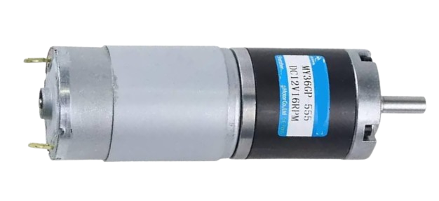
A Direct Current (DC) motor is an electronic component that converts direct current electrical energy into mechanical energy. It operates on the basic principle that a current-carrying conductor is placed within a magnetic field, which causes it to experience a force and thus create motion. DC motors are widely used in various applications such as electric vehicles, industrial machinery, robotics, and consumer electronics due to their simplicity, reliability, and ease of control.

Explore Projects Built with dc

Use Cirkit Designer to design, explore, and prototype these projects online. Some projects support real-time simulation. Click "Open Project" to start designing instantly!
USB-Powered DC Gear Motor with LED Indicator
Image of Hand Crank mobile charger : A project utilizing dc  in a practical application
This circuit appears to be a power supply unit with a bridge rectifier connected to a DC gear motor, indicating it is designed to convert AC to DC power for the motor. An electrolytic capacitor is used for smoothing the DC output, and a 7805 voltage regulator is included to provide a stable 5V output. Additionally, there is an LED with a series resistor, likely serving as a power indicator light.
Cirkit Designer LogoOpen Project in Cirkit Designer
Modular DC Power Distribution System
Image of battery: A project utilizing dc  in a practical application
The circuit consists of multiple DC power sources. All the power sources are divided into groups, with each group having their positive terminals connected together and their ground terminals connected together, forming independent parallel voltage sources within each group. There is no further interconnection between these groups or any other components, indicating that this could be a modular setup for providing multiple independent power supplies.
Cirkit Designer LogoOpen Project in Cirkit Designer
Quad DC Motor Control with LED Indicator and Rocker Switch
Image of arul 7c to 8th school exhibition wind 1 side: A project utilizing dc  in a practical application
This circuit features multiple DC motors connected in series, powered by parallel-connected 9V batteries. A rocker switch is used to control a 12V blue LED, which likely serves as a power indicator for the circuit.
Cirkit Designer LogoOpen Project in Cirkit Designer
Arduino UNO Controlled 8-Motor System with Keypad and DFPlayer Mini
Image of Copy of medicine dispenser: A project utilizing dc  in a practical application
This circuit uses an Arduino UNO to control eight DC motors via an 8-channel relay module, based on user input from a 4x4 membrane keypad. Additionally, a DFPlayer Mini MP3 player is integrated to provide audio feedback through a loudspeaker, with all components powered by a 12V battery.
Cirkit Designer LogoOpen Project in Cirkit Designer

Explore Projects Built with dc

Use Cirkit Designer to design, explore, and prototype these projects online. Some projects support real-time simulation. Click "Open Project" to start designing instantly!
Image of Hand Crank mobile charger : A project utilizing dc  in a practical application
USB-Powered DC Gear Motor with LED Indicator
This circuit appears to be a power supply unit with a bridge rectifier connected to a DC gear motor, indicating it is designed to convert AC to DC power for the motor. An electrolytic capacitor is used for smoothing the DC output, and a 7805 voltage regulator is included to provide a stable 5V output. Additionally, there is an LED with a series resistor, likely serving as a power indicator light.
Cirkit Designer LogoOpen Project in Cirkit Designer
Image of battery: A project utilizing dc  in a practical application
Modular DC Power Distribution System
The circuit consists of multiple DC power sources. All the power sources are divided into groups, with each group having their positive terminals connected together and their ground terminals connected together, forming independent parallel voltage sources within each group. There is no further interconnection between these groups or any other components, indicating that this could be a modular setup for providing multiple independent power supplies.
Cirkit Designer LogoOpen Project in Cirkit Designer
Image of arul 7c to 8th school exhibition wind 1 side: A project utilizing dc  in a practical application
Quad DC Motor Control with LED Indicator and Rocker Switch
This circuit features multiple DC motors connected in series, powered by parallel-connected 9V batteries. A rocker switch is used to control a 12V blue LED, which likely serves as a power indicator for the circuit.
Cirkit Designer LogoOpen Project in Cirkit Designer
Image of Copy of medicine dispenser: A project utilizing dc  in a practical application
Arduino UNO Controlled 8-Motor System with Keypad and DFPlayer Mini
This circuit uses an Arduino UNO to control eight DC motors via an 8-channel relay module, based on user input from a 4x4 membrane keypad. Additionally, a DFPlayer Mini MP3 player is integrated to provide audio feedback through a loudspeaker, with all components powered by a 12V battery.
Cirkit Designer LogoOpen Project in Cirkit Designer

Common Applications and Use Cases

  • Robotics: Actuation of robotic limbs and wheels.
  • Consumer Electronics: Drives in computer disk drives, fans, and vibrators in mobile phones.
  • Automotive: Fuel pump controllers, power windows, and seat adjusters.
  • Industrial Control: Conveyor systems, hoists, and process control applications.

Technical Specifications

Key Technical Details

  • Voltage Range: Typically 1.5V to 300V DC
  • Current Rating: Varies with size and model, from mA to hundreds of Amperes
  • Power Ratings: From milliwatts to several kilowatts
  • Speed: Typically from 1000 RPM to 15000 RPM for small motors

Pin Configuration and Descriptions

Pin Number Description Notes
1 Positive Supply (V+) Connect to positive voltage
2 Negative Supply (GND) Connect to ground

Usage Instructions

How to Use the Component in a Circuit

  1. Power Supply Connection: Connect the positive terminal of the DC motor to the positive voltage supply and the negative terminal to the ground.
  2. Speed Control: To control the speed of the DC motor, a Pulse Width Modulation (PWM) signal can be applied to the positive terminal.
  3. Direction Control: To change the direction of the motor, reverse the polarity of the voltage applied to the motor terminals.

Important Considerations and Best Practices

  • Voltage Rating: Do not exceed the voltage rating of the motor as it can cause overheating and damage.
  • Current Draw: Ensure the power supply can handle the motor's current draw, especially during startup.
  • Motor Driver: Use a motor driver or H-bridge to interface the motor with microcontrollers for better control and to protect the microcontroller from high current.
  • Flyback Diode: Always use a flyback diode across the motor terminals to protect the circuit from voltage spikes when the motor is turned off.

Troubleshooting and FAQs

Common Issues Users Might Face

  • Motor not spinning: Check if the power supply is connected correctly and if it provides sufficient voltage and current.
  • Motor overheating: Ensure the motor is not overloaded and that it operates within its rated voltage and current.

Solutions and Tips for Troubleshooting

  • Check Connections: Verify that all connections are secure and correct.
  • Measure Voltage and Current: Use a multimeter to ensure the motor is receiving the correct voltage and current.
  • Inspect for Physical Damage: Look for signs of damage or wear on the motor that could impede its operation.

FAQs

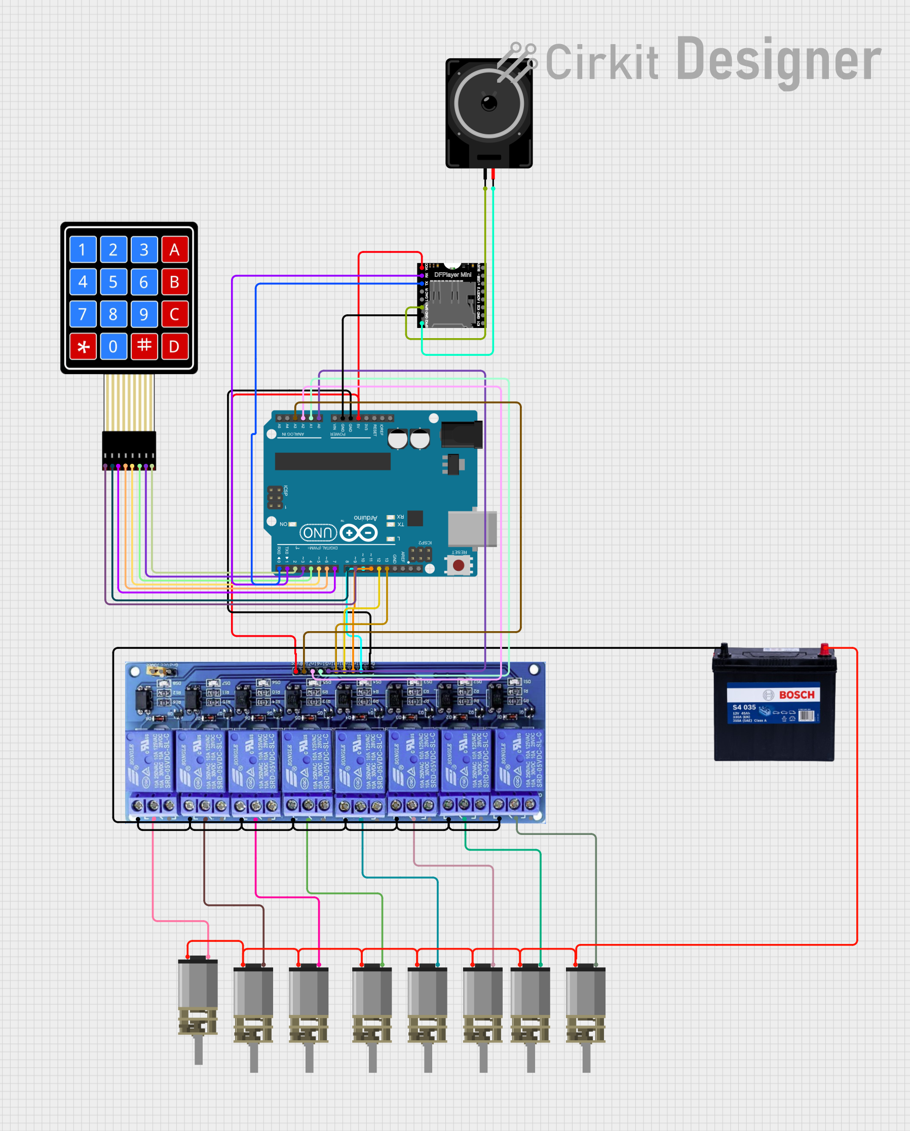
Q: Can I control a DC motor using an Arduino? A: Yes, you can control a DC motor using an Arduino by using a motor driver and PWM signals.

Q: What is the purpose of a flyback diode? A: A flyback diode is used to protect the circuit from voltage spikes caused by the inductive load of the motor when it is turned off.

Q: How can I reverse the direction of a DC motor? A: You can reverse the direction by reversing the polarity of the voltage applied to the motor's terminals.

Example Code for Arduino UNO

// Example code to control a DC motor with an Arduino UNO
#include <Arduino.h>

const int motorPin = 3; // PWM pin connected to the DC motor

void setup() {
  pinMode(motorPin, OUTPUT); // Set motor pin as output
}

void loop() {
  analogWrite(motorPin, 127); // Set speed (0-255)
  delay(1000);                // Run motor for 1 second
  analogWrite(motorPin, 0);   // Stop motor
  delay(1000);                // Wait for 1 second
}

Note: This example assumes the use of a motor driver or H-bridge connected to the motor and the Arduino. The analogWrite function sends a PWM signal to control the motor speed. Always ensure that the motor driver is compatible with the motor's voltage and current specifications.