The TINY RTC is a compact real-time clock (RTC) module designed to keep track of the current time and date. It is widely used in microcontroller projects to maintain accurate timekeeping, even when the main power supply is disconnected. This is achieved through the use of a backup battery, which ensures continuous operation. The module is based on the DS1307 RTC chip and is commonly paired with microcontrollers like Arduino, Raspberry Pi, and others.
Explore Projects Built with TINY RTC
Use Cirkit Designer to design, explore, and prototype these projects online. Some projects support real-time simulation. Click "Open Project" to start designing instantly!
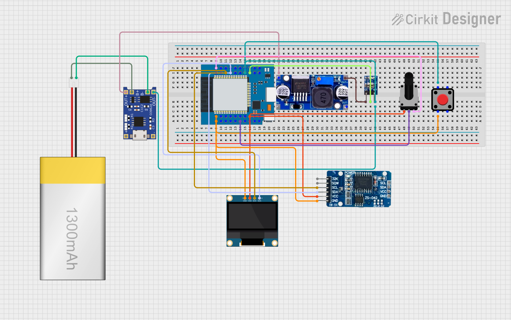
This circuit features an ESP32 Mini microcontroller as its core, interfaced with a 0.96" OLED display and a DS3231 Real-Time Clock (RTC) for timekeeping and display purposes. A TP4056 module is used for charging a LiPoly battery, which powers the system through an LM2596 voltage regulator and an AMS1117-3.3 voltage regulator to step down and stabilize the voltage for the ESP32 and peripherals. User inputs are captured through a rotary potentiometer and a red pushbutton, which are connected to the ESP32's GPIOs for control and reset functionality.
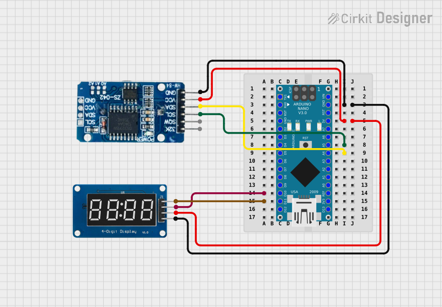
This circuit features an Arduino Nano interfacing with a DS3231 Real-Time Clock for timekeeping and a TM1637 display module for visual output. The Arduino facilitates I2C communication with the RTC and controls the display using digital IO, serving as the central processing unit for a digital clock or timer application.
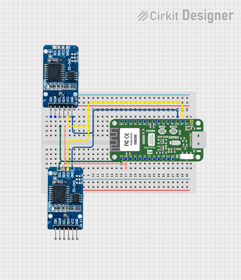
This circuit integrates two RTC DS3231 real-time clock modules with a Glyph C3 microcontroller. The RTC modules are connected to the microcontroller via I2C communication protocol, using the SCL and SDA lines for clock and data respectively. Both RTC modules and the microcontroller share a common power supply (3V3) and ground (GND), indicating that they operate at the same voltage level.
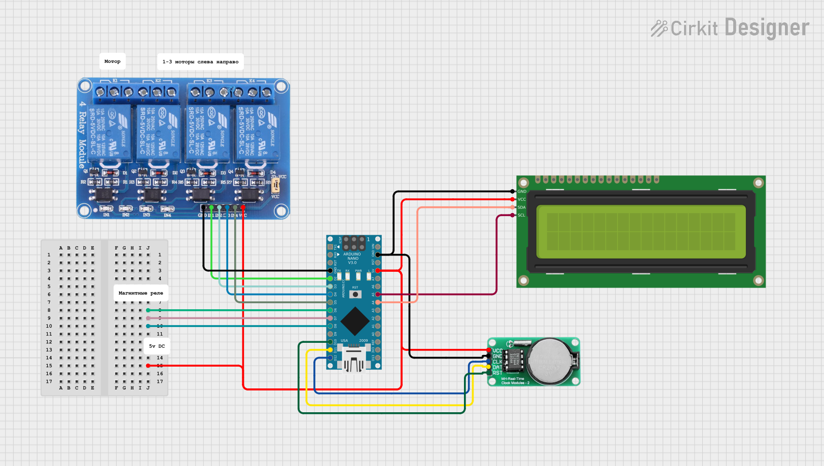
This circuit features an Arduino Nano microcontroller interfaced with a DS1302 RTC module for real-time clock functionality, a 16x2 I2C LCD for display, and a 4-channel relay module for controlling external devices. The Arduino Nano manages the RTC and displays the time on the LCD while controlling the relays through digital pins.
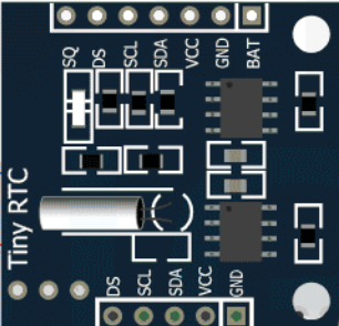
The TINY RTC module is built around the DS1307 RTC chip and includes additional components like a backup battery and pull-up resistors for I2C communication. Below are the key technical details:
Key Technical Details
Chipset: DS1307 Real-Time Clock IC
Communication Protocol: I2C (Inter-Integrated Circuit)
Operating Voltage: 5V DC
Backup Battery: CR2032 coin cell (3V)
Timekeeping Accuracy: ±2 seconds/day (typical)
Time Format: 24-hour or 12-hour with AM/PM
Temperature Range: 0°C to +70°C (operating)
Memory: 56 bytes of non-volatile RAM for user data
Pin Configuration and Descriptions
The TINY RTC module typically has a 4-pin interface for I2C communication. Below is the pinout:
Pin
Name
Description
1
VCC
Power supply input (5V DC)
2
GND
Ground connection
3
SDA
Serial Data Line for I2C communication
4
SCL
Serial Clock Line for I2C communication
Usage Instructions
How to Use the TINY RTC in a Circuit
Connect the Module:
Connect the VCC pin to the 5V output of your microcontroller.
Connect the GND pin to the ground of your microcontroller.
Connect the SDA pin to the I2C data line of your microcontroller.
Connect the SCL pin to the I2C clock line of your microcontroller.
Install the Backup Battery:
Insert a CR2032 coin cell battery into the battery holder on the module. This ensures the RTC continues to keep time even when the main power is off.
Include the Required Libraries:
For Arduino, use the RTClib library, which provides easy-to-use functions for the DS1307.
Write and Upload Code:
Use the example code below to initialize the RTC and read the current time and date.
Example Code for Arduino UNO
#include <Wire.h>
#include <RTClib.h>

// Create an RTC object
RTC_DS1307 rtc;

void setup() {
  Serial.begin(9600); // Initialize serial communication
  Wire.begin();       // Initialize I2C communication

  if (!rtc.begin()) {
    Serial.println("Couldn't find RTC. Check connections!");
    while (1); // Halt execution if RTC is not found
  }

  if (!rtc.isrunning()) {
    Serial.println("RTC is not running. Setting the time...");
    rtc.adjust(DateTime(F(__DATE__), F(__TIME__)));
    // Sets the RTC to the date & time of compilation
  }
}

void loop() {
  DateTime now = rtc.now(); // Get the current time and date

  // Print the current time and date to the Serial Monitor
  Serial.print(now.year(), DEC);
  Serial.print('/');
  Serial.print(now.month(), DEC);
  Serial.print('/');
  Serial.print(now.day(), DEC);
  Serial.print(" ");
  Serial.print(now.hour(), DEC);
  Serial.print(':');
  Serial.print(now.minute(), DEC);
  Serial.print(':');
  Serial.print(now.second(), DEC);
  Serial.println();

  delay(1000); // Wait for 1 second before updating
}
Important Considerations and Best Practices
Ensure the backup battery is installed correctly to maintain timekeeping during power loss.
Avoid shorting the battery terminals, as this can damage the module.
Use pull-up resistors on the I2C lines if they are not already included on the module.
Verify the I2C address of the module (default is 0x68) if using multiple I2C devices.
Troubleshooting and FAQs
Common Issues and Solutions
RTC Not Detected:
Cause: Loose or incorrect wiring.
Solution: Double-check the connections, especially the SDA and SCL lines.
Incorrect Time or Date:
Cause: RTC not initialized or backup battery is depleted.
Solution: Use the rtc.adjust() function to set the correct time and replace the battery if necessary.
I2C Communication Errors:
Cause: Address conflict or missing pull-up resistors.
Solution: Ensure the I2C address is correct and add pull-up resistors if needed.
RTC Stops Keeping Time After Power Loss:
Cause: Backup battery is missing or dead.
Solution: Install a new CR2032 battery.
FAQs
Q: Can the TINY RTC module work with 3.3V microcontrollers?
A: The DS1307 chip requires a 5V power supply. Use a level shifter for I2C lines if interfacing with a 3.3V microcontroller.
Q: How long does the backup battery last?
A: A typical CR2032 battery can last for several years, depending on usage and environmental conditions.
Q: Can I use the TINY RTC module to store custom data?
A: Yes, the DS1307 includes 56 bytes of non-volatile RAM that can be used to store user data.
Q: What is the default I2C address of the TINY RTC module?
A: The default I2C address is 0x68.

 Open Project in Cirkit Designer