
How to Use ECU: Examples, Pinouts, and Specs
 Design with ECU in Cirkit Designer
Introduction
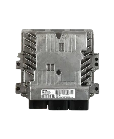
The Electronic Control Unit (ECU), manufactured by CAR (Part ID: CAR), is a digital computer designed to manage and control various functions in a vehicle. It plays a critical role in modern automotive systems by ensuring optimal performance, safety, and efficiency. The ECU is responsible for tasks such as engine management, transmission control, and monitoring other essential vehicle systems.
Explore Projects Built with ECU
 Open Project in Cirkit Designer
 Open Project in Cirkit Designer
 Open Project in Cirkit Designer
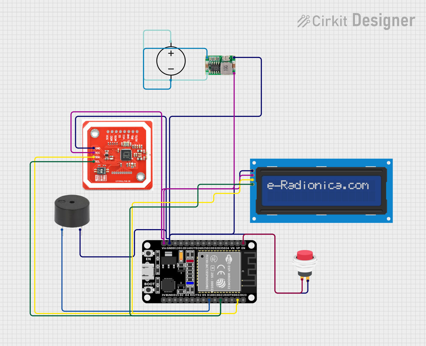 Open Project in Cirkit Designer
Explore Projects Built with ECU
Open Project in Cirkit DesignerOpen Project in Cirkit DesignerOpen Project in Cirkit DesignerOpen Project in Cirkit DesignerCommon Applications and Use Cases
- Engine Management: Controls fuel injection, ignition timing, and air-fuel mixture for optimal engine performance.
- Transmission Control: Manages gear shifting in automatic transmissions.
- Safety Systems: Interfaces with airbags, anti-lock braking systems (ABS), and traction control.
- Diagnostics: Monitors and logs fault codes for troubleshooting vehicle issues.
- Emission Control: Ensures compliance with environmental regulations by managing exhaust systems.
Technical Specifications
The following table outlines the key technical specifications of the ECU:
| Parameter | Specification |
|---|---|
| Operating Voltage | 12V DC (nominal), 9V-16V range |
| Power Consumption | 5W-50W (depending on system load) |
| Communication Protocol | CAN, LIN, or FlexRay |
| Processor Type | 32-bit microcontroller |
| Memory | Flash: 1MB-4MB, RAM: 256KB-1MB |
| Operating Temperature | -40°C to +85°C |
| Dimensions | Varies by model (e.g., 150mm x 100mm x 30mm) |
Pin Configuration and Descriptions
The ECU typically features a multi-pin connector for interfacing with vehicle systems. Below is an example of a generic pin configuration:
| Pin Number | Pin Name | Description |
|---|---|---|
| 1 | Power (+12V) | Main power supply input |
| 2 | Ground (GND) | Ground connection |
| 3 | CAN_H | High line for CAN communication |
| 4 | CAN_L | Low line for CAN communication |
| 5 | Ignition Signal | Detects ignition status |
| 6 | Sensor Input 1 | Analog input from a connected sensor |
| 7 | Sensor Input 2 | Analog input from another connected sensor |
| 8 | Actuator Control 1 | Output signal to control an actuator |
| 9 | Actuator Control 2 | Output signal to control another actuator |
| 10 | Diagnostic Line | Used for on-board diagnostics (OBD) communication |
Note: Pin configurations may vary depending on the specific ECU model and vehicle manufacturer.
Usage Instructions
How to Use the ECU in a Vehicle
Installation:
- Mount the ECU securely in the designated location within the vehicle.
- Ensure proper grounding to avoid electrical noise or interference.
- Connect the ECU to the vehicle's wiring harness using the appropriate connector.
Power Supply:
- Verify that the ECU receives a stable 12V DC power supply.
- Check for proper grounding to prevent voltage fluctuations.
Communication:
- Connect the CAN_H and CAN_L pins to the vehicle's CAN bus for communication with other modules.
- Use diagnostic tools to verify communication and read fault codes.
Sensor and Actuator Connections:
- Connect sensors (e.g., temperature, pressure) to the designated input pins.
- Connect actuators (e.g., fuel injectors, throttle control) to the output pins.
Important Considerations and Best Practices
- Firmware Updates: Ensure the ECU firmware is up-to-date to maintain compatibility with the vehicle's systems.
- Diagnostics: Use an OBD-II scanner to monitor ECU performance and troubleshoot issues.
- Environmental Protection: Protect the ECU from moisture, extreme temperatures, and vibrations.
- Wiring: Avoid loose or damaged wiring to prevent communication errors or malfunctions.
Example: Reading Data from the ECU with Arduino UNO
The ECU can communicate with external devices like an Arduino UNO via the CAN protocol. Below is an example code snippet for reading data from the ECU:
#include <SPI.h>
#include <mcp_can.h>

// Define the CAN bus pins for the MCP2515 module
#define CAN_CS 10  // Chip Select pin
#define CAN_INT 2  // Interrupt pin

MCP_CAN CAN(CAN_CS);  // Create CAN object

void setup() {
  Serial.begin(9600);  // Initialize serial communication
  while (!Serial);

  // Initialize the CAN bus at 500 kbps
  if (CAN.begin(MCP_ANY, 500000, MCP_8MHZ) == CAN_OK) {
    Serial.println("CAN bus initialized successfully!");
  } else {
    Serial.println("Error initializing CAN bus.");
    while (1);
  }

  CAN.setMode(MCP_NORMAL);  // Set CAN bus to normal mode
  pinMode(CAN_INT, INPUT);  // Set interrupt pin as input
}

void loop() {
  long unsigned int id;  // Variable to store CAN ID
  unsigned char len;     // Variable to store data length
  unsigned char buf[8];  // Buffer to store received data

  // Check if data is available on the CAN bus
  if (CAN.checkReceive() == CAN_MSGAVAIL) {
    CAN.readMsgBuf(&id, &len, buf);  // Read data from the CAN bus

    // Print the received CAN ID and data
    Serial.print("ID: 0x");
    Serial.print(id, HEX);
    Serial.print(" Data: ");
    for (int i = 0; i < len; i++) {
      Serial.print(buf[i], HEX);
      Serial.print(" ");
    }
    Serial.println();
  }
}
Note: This example assumes the use of an MCP2515 CAN module. Adjust the code as needed for your specific setup.
Troubleshooting and FAQs
Common Issues and Solutions
ECU Not Powering On:
- Cause: Faulty power supply or loose connections.
- Solution: Check the power and ground connections. Verify the voltage at the ECU input.
Communication Errors:
- Cause: Incorrect CAN bus wiring or baud rate mismatch.
- Solution: Verify the CAN_H and CAN_L connections. Ensure the baud rate matches the ECU's settings.
Fault Codes Persist:
- Cause: Unresolved issues in connected systems.
- Solution: Use a diagnostic tool to identify and address the root cause of the fault.
Overheating:
- Cause: Poor ventilation or excessive load.
- Solution: Ensure proper airflow around the ECU. Check for short circuits or overloaded outputs.
FAQs
Q: Can I use the ECU with a 24V system?
A: No, the ECU is designed for 12V systems. Using a 24V system may damage the unit.Q: How do I reset the ECU?
A: Disconnect the power supply for 10-15 minutes, then reconnect it. This will reset the ECU.Q: Can the ECU be reprogrammed?
A: Yes, the ECU firmware can be updated or reprogrammed using specialized tools provided by the manufacturer.Q: What happens if the ECU fails?
A: A failed ECU can cause various issues, such as engine misfires, poor performance, or complete vehicle inoperability. Replace or repair the ECU as needed.
This concludes the documentation for the Electronic Control Unit (ECU) by CAR.