How to Use RS485 CAN HAT for Raspberry Pi: Examples, Pinouts, and Specs
Introduction
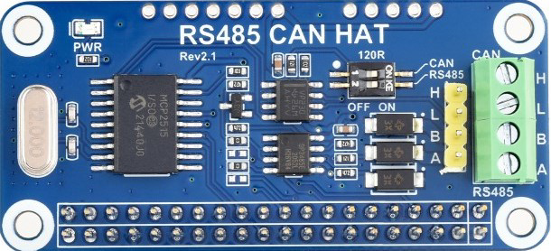
The RS485 CAN HAT by Waveshare (Part ID: RS485 CAN HAT) is a hardware add-on designed for Raspberry Pi boards. It enables communication over RS485 and CAN bus protocols, which are widely used in industrial automation, automotive systems, and other robust data transmission applications. This HAT provides a reliable and efficient way to interface your Raspberry Pi with devices that use these communication standards.
Explore Projects Built with RS485 CAN HAT for Raspberry Pi

Explore Projects Built with RS485 CAN HAT for Raspberry Pi
Common Applications and Use Cases
- Industrial automation and control systems
- Automotive diagnostics and communication
- Home automation and building management systems
- Robotics and sensor networks
- Data logging and monitoring in harsh environments
Technical Specifications
The RS485 CAN HAT is equipped with high-performance transceivers and features that ensure reliable communication. Below are the key technical details:
General Specifications
| Parameter | Value |
|---|---|
| Communication Protocols | RS485, CAN |
| Operating Voltage | 3.3V/5V (via Raspberry Pi GPIO) |
| Baud Rate (RS485) | Up to 115200 bps |
| Baud Rate (CAN) | Up to 1 Mbps |
| Operating Temperature | -40°C to 85°C |
| Dimensions | 65mm × 30mm |
Pin Configuration and Descriptions
The RS485 CAN HAT connects to the Raspberry Pi via the GPIO header. Below is the pin configuration:
GPIO Pin Mapping
| Pin Name | GPIO Pin | Description |
|---|---|---|
| TXD | GPIO14 | UART Transmit for RS485 |
| RXD | GPIO15 | UART Receive for RS485 |
| CAN_TX | GPIO12 | CAN Transmit |
| CAN_RX | GPIO13 | CAN Receive |
| RTS | GPIO17 | RS485 Transmit Enable |
| INT | GPIO25 | Interrupt for CAN |
| 3.3V | 3.3V | Power Supply (3.3V) |
| 5V | 5V | Power Supply (5V) |
| GND | GND | Ground |
RS485 and CAN Terminals
| Terminal Name | Description |
|---|---|
| A (RS485) | RS485 Data Line A (Non-inverting) |
| B (RS485) | RS485 Data Line B (Inverting) |
| CAN_H | CAN High Line |
| CAN_L | CAN Low Line |
Usage Instructions
The RS485 CAN HAT is easy to set up and use with a Raspberry Pi. Follow the steps below to get started:
Step 1: Hardware Setup
- Attach the HAT: Align the RS485 CAN HAT with the Raspberry Pi GPIO header and press it down gently.
- Connect the Terminals:
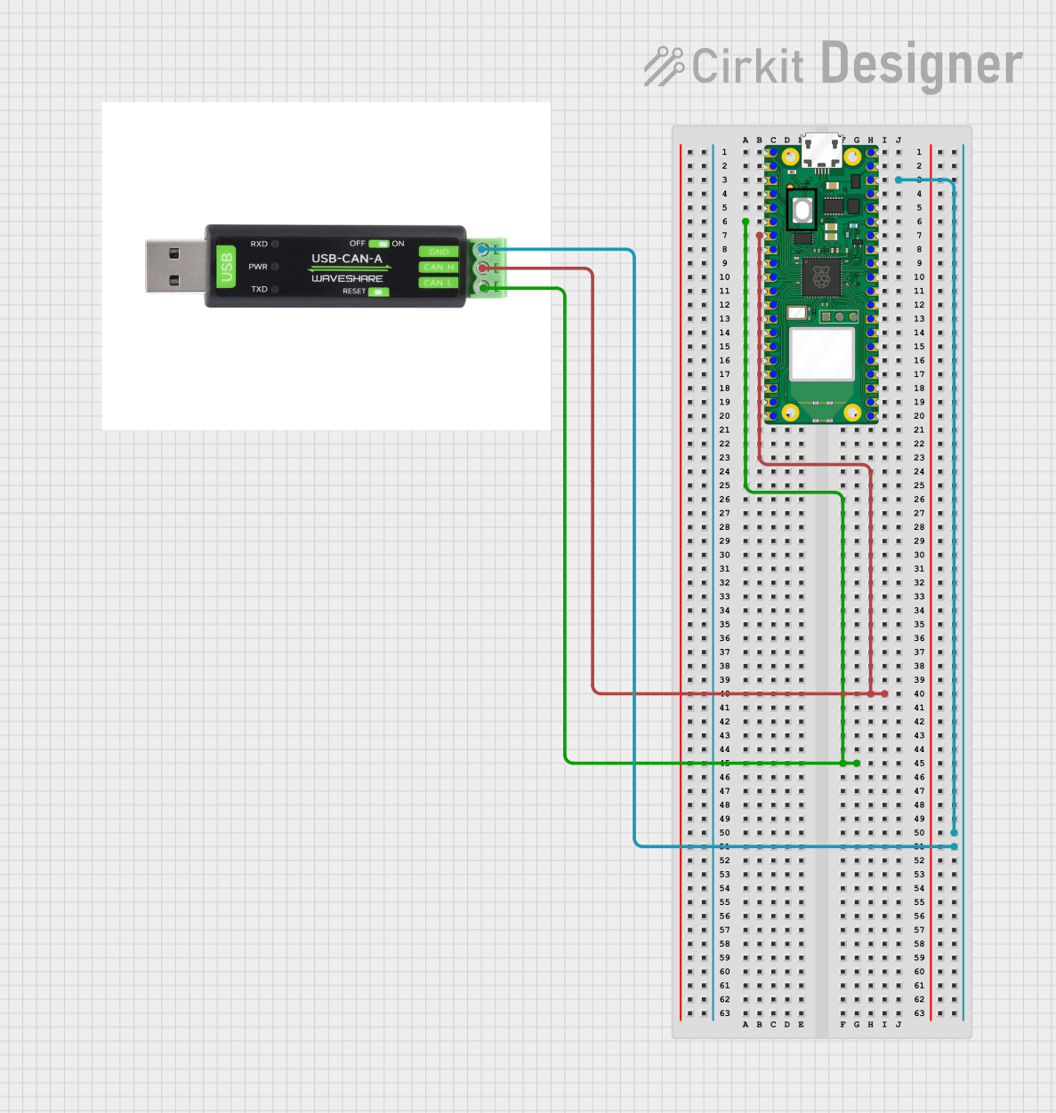
- For RS485: Connect the A and B terminals to the corresponding RS485 device.
- For CAN: Connect the CAN_H and CAN_L terminals to the CAN bus.
- Enable Termination Resistors (if required):
- Use the onboard jumpers to enable or disable termination resistors for RS485 and CAN.
Step 2: Software Setup
- Install Required Libraries:
- Update your Raspberry Pi:
sudo apt update && sudo apt upgrade - Install the Python libraries for RS485 and CAN communication:
sudo apt install python3-pip
pip3 install can pyserial
- Update your Raspberry Pi:
- Enable UART and SPI:
- Open the Raspberry Pi configuration tool:
sudo raspi-config - Navigate to
Interface Optionsand enableSerial PortandSPI.
- Open the Raspberry Pi configuration tool:
Step 3: Example Code
RS485 Communication Example
The following Python code demonstrates how to send and receive data over RS485:
import serial
Initialize the RS485 serial connection
Replace '/dev/ttyS0' with the correct UART port for your Raspberry Pi
rs485 = serial.Serial( port='/dev/ttyS0', # UART port baudrate=115200, # Baud rate timeout=1 # Timeout in seconds )
try: # Send data over RS485 rs485.write(b'Hello RS485!\n') print("Data sent: Hello RS485!")
# Receive data over RS485
received_data = rs485.readline().decode('utf-8').strip()
print(f"Data received: {received_data}")
except Exception as e: print(f"Error: {e}")
finally: rs485.close() # Close the serial connection
CAN Communication Example
The following Python code demonstrates how to send and receive data over CAN:
import can
Initialize the CAN bus
Replace 'can0' with the correct CAN interface for your setup
bus = can.interface.Bus(channel='can0', bustype='socketcan')
try: # Send a CAN message message = can.Message(arbitration_id=0x123, data=[0x01, 0x02, 0x03, 0x04], is_extended_id=False) bus.send(message) print("CAN message sent: ID=0x123, Data=[0x01, 0x02, 0x03, 0x04]")
# Receive a CAN message
received_message = bus.recv(timeout=1.0)  # Wait for 1 second
if received_message:
    print(f"CAN message received: ID={hex(received_message.arbitration_id)}, "
          f"Data={received_message.data}")
except Exception as e: print(f"Error: {e}")
finally: bus.shutdown() # Shutdown the CAN bus
Important Considerations
- Ensure the Raspberry Pi and connected devices share a common ground.
- Use appropriate termination resistors for RS485 and CAN bus to prevent signal reflections.
- Verify the baud rate and other communication parameters match between devices.
Troubleshooting and FAQs
Common Issues
No Data Transmission or Reception:
- Ensure the HAT is properly seated on the Raspberry Pi GPIO header.
- Verify the wiring of RS485 (A and B) or CAN (CAN_H and CAN_L) terminals.
- Check that the correct UART or CAN interface is being used in the code.
Data Corruption:
- Confirm that the baud rate and other communication settings match between devices.
- Use proper shielding for cables in noisy environments.
CAN Bus Errors:
- Ensure termination resistors are enabled at both ends of the CAN bus.
- Check for bus conflicts or incorrect arbitration IDs.
FAQs
Q: Can I use this HAT with other single-board computers?
A: The HAT is designed for Raspberry Pi, but it may work with other boards that have compatible GPIO headers and software support.
Q: What is the maximum cable length for RS485 and CAN?
A: RS485 supports up to 1200 meters, while CAN typically supports up to 40 meters at 1 Mbps (longer distances are possible at lower baud rates).
Q: How do I enable termination resistors?
A: Use the onboard jumpers to enable or disable the termination resistors for RS485 and CAN.
By following this documentation, you can effectively use the RS485 CAN HAT for robust communication in your projects.