How to Use 3.5 inch ESP32-S3 Display module: Examples, Pinouts, and Specs
Introduction
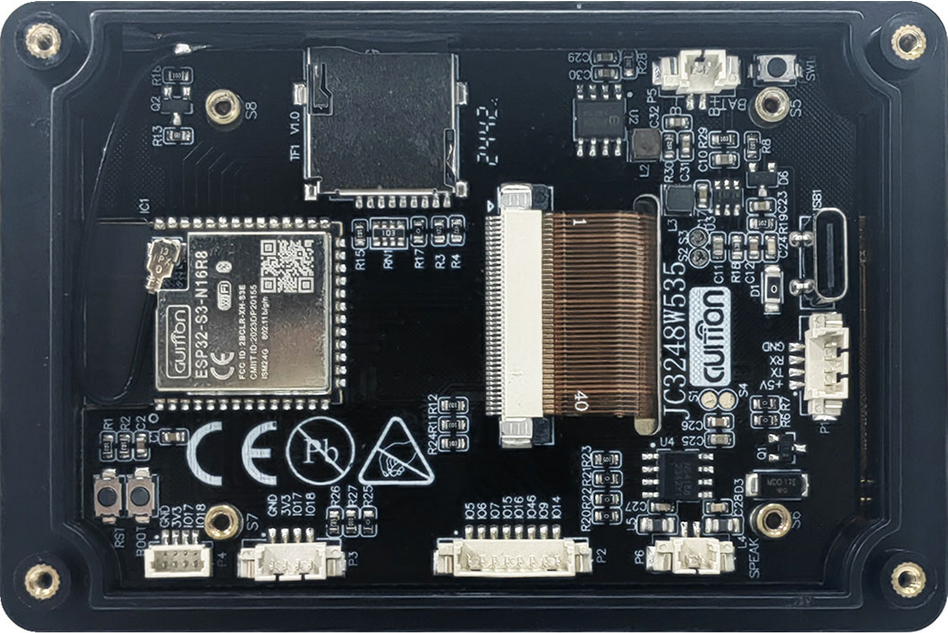
The 3.5 inch ESP32-S3 Display Module (Manufacturer Part ID: JC3248W535C_I_Y) by Shenzhen Jingcai Intelligent is a compact and versatile display module. It features a 3.5-inch touchscreen interface and is powered by the ESP32-S3 microcontroller, which supports both Wi-Fi and Bluetooth connectivity. This module is designed for IoT applications, interactive projects, and embedded systems requiring a graphical user interface.
Explore Projects Built with 3.5 inch ESP32-S3 Display module


Explore Projects Built with 3.5 inch ESP32-S3 Display module
Common Applications and Use Cases
- IoT dashboards and control panels
- Smart home devices with touch interfaces
- Industrial monitoring systems
- Educational and prototyping projects
- Portable devices with wireless connectivity
- Interactive kiosks and displays
Technical Specifications
Key Technical Details
| Parameter | Specification |
|---|---|
| Display Size | 3.5 inches |
| Resolution | 480 x 320 pixels |
| Touchscreen Type | Capacitive |
| Microcontroller | ESP32-S3 |
| Connectivity | Wi-Fi 802.11 b/g/n, Bluetooth 5.0 |
| Operating Voltage | 3.3V |
| Power Consumption | ~200mA (typical) |
| Interface | SPI |
| Flash Memory | 16MB |
| PSRAM | 8MB |
| Dimensions | 85mm x 55mm x 10mm |
| Operating Temperature | -20°C to 70°C |
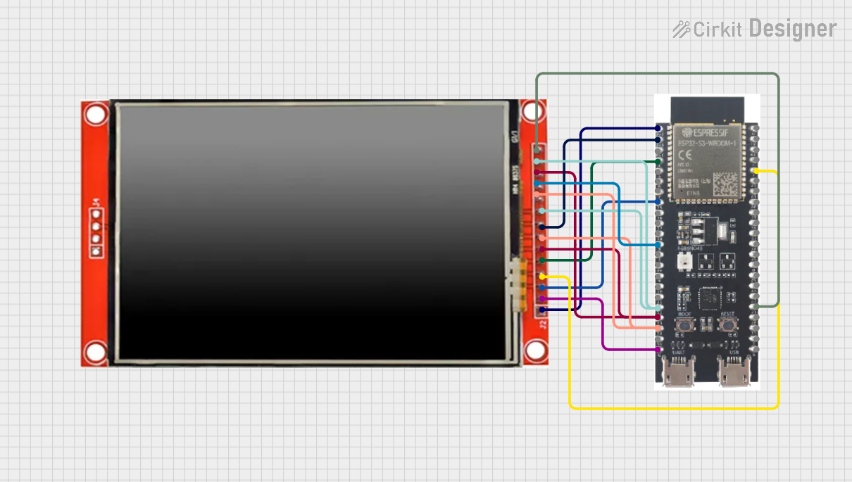
Pin Configuration and Descriptions
The module has a 16-pin interface for power, communication, and control. Below is the pinout:
| Pin Number | Pin Name | Description |
|---|---|---|
| 1 | GND | Ground connection |
| 2 | VCC | Power supply input (3.3V) |
| 3 | MISO | SPI Master-In-Slave-Out (data from module to MCU) |
| 4 | MOSI | SPI Master-Out-Slave-In (data from MCU to module) |
| 5 | SCK | SPI Clock |
| 6 | CS | Chip Select (active low) |
| 7 | DC | Data/Command control signal |
| 8 | RST | Reset signal (active low) |
| 9 | T_IRQ | Touchscreen interrupt signal |
| 10 | T_CS | Touchscreen chip select (active low) |
| 11 | TXD | UART Transmit (for debugging or communication) |
| 12 | RXD | UART Receive (for debugging or communication) |
| 13 | EN | Enable pin for ESP32-S3 (active high) |
| 14 | GPIO0 | General-purpose I/O pin (used for boot mode selection during programming) |
| 15 | GPIO1 | General-purpose I/O pin |
| 16 | GPIO2 | General-purpose I/O pin |
Usage Instructions
How to Use the Component in a Circuit
- Power Supply: Connect the VCC pin to a 3.3V power source and GND to ground.
- SPI Communication: Connect the SPI pins (MISO, MOSI, SCK, CS) to the corresponding SPI pins on your microcontroller.
- Touchscreen Control: Use the T_CS and T_IRQ pins to interface with the touchscreen controller.
- Reset and Enable: Connect the RST pin to a GPIO pin for resetting the module and the EN pin to 3.3V or a GPIO pin for enabling the ESP32-S3.
- UART Debugging: Optionally, connect TXD and RXD to a UART interface for debugging or serial communication.
Important Considerations and Best Practices
- Voltage Levels: Ensure all GPIO pins interfacing with the module operate at 3.3V logic levels to avoid damage.
- Power Supply: Use a stable 3.3V power source capable of supplying at least 300mA to ensure reliable operation.
- SPI Speed: Configure the SPI clock speed to a maximum of 40MHz for optimal performance.
- Touchscreen Calibration: If using the touchscreen, ensure proper calibration in your software for accurate touch detection.
- Firmware Updates: Keep the ESP32-S3 firmware updated to the latest version for improved performance and security.
Example Code for Arduino UNO
Below is an example of how to interface the module with an Arduino UNO using the SPI interface. Note that the Arduino UNO operates at 5V logic, so a level shifter is required for compatibility.
#include <SPI.h>
#include <TFT_eSPI.h> // Library for the display
#include <Wire.h>

// Define SPI pins for the display
#define TFT_CS   10  // Chip select pin
#define TFT_DC   9   // Data/Command pin
#define TFT_RST  8   // Reset pin

// Create an instance of the TFT_eSPI library
TFT_eSPI tft = TFT_eSPI();

void setup() {
  // Initialize serial communication for debugging
  Serial.begin(115200);
  Serial.println("Initializing 3.5 inch ESP32-S3 Display Module...");

  // Initialize the display
  tft.init();
  tft.setRotation(1); // Set display orientation (1 = landscape)

  // Clear the screen and set background color
  tft.fillScreen(TFT_BLACK);
  tft.setTextColor(TFT_WHITE, TFT_BLACK);
  tft.setTextSize(2);

  // Display a welcome message
  tft.setCursor(10, 10);
  tft.println("Hello, World!");
}

void loop() {
  // Example: Draw a rectangle on the screen
  tft.fillRect(50, 50, 100, 50, TFT_BLUE);
  delay(1000);

  // Clear the rectangle
  tft.fillRect(50, 50, 100, 50, TFT_BLACK);
  delay(1000);
}
Note: Replace the TFT_eSPI library configuration file with the correct pin mappings for your setup.
Troubleshooting and FAQs
Common Issues and Solutions
Display Not Turning On:
- Ensure the VCC and GND pins are properly connected.
- Verify that the power supply provides a stable 3.3V.
No Response from Touchscreen:
- Check the T_CS and T_IRQ connections.
- Ensure the touchscreen library is correctly configured in your code.
Flickering or Artifacts on Display:
- Reduce the SPI clock speed in your code.
- Check for loose or poor-quality connections.
ESP32-S3 Not Responding:
- Verify the EN pin is pulled high.
- Check the RST pin and ensure it is not held low.
FAQs
Q1: Can this module be powered with 5V?
A1: No, the module operates at 3.3V. Use a voltage regulator or level shifter if interfacing with 5V systems.
Q2: Is the touchscreen resistive or capacitive?
A2: The touchscreen is capacitive, providing multi-touch support and high accuracy.
Q3: Can I use this module with platforms other than Arduino?
A3: Yes, the module is compatible with other platforms like ESP-IDF, Raspberry Pi, and STM32, provided the appropriate libraries and drivers are used.
Q4: How do I update the ESP32-S3 firmware?
A4: Use the ESP32-S3's USB interface or UART pins with the ESP-IDF or Arduino IDE to upload new firmware.
Q5: What is the maximum Wi-Fi range of the ESP32-S3?
A5: The Wi-Fi range depends on environmental factors but typically extends up to 50 meters indoors and 200 meters outdoors.