How to Use TP5100: Examples, Pinouts, and Specs
Introduction
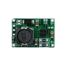
The TP5100 is a high-efficiency linear voltage regulator designed to deliver a stable output voltage with a low dropout. Manufactured by TP, this component is widely used in battery-powered devices due to its compact design, high efficiency, and robust protection features. The TP5100 integrates thermal protection, current limiting, and other safety mechanisms, making it a reliable choice for various applications.
Explore Projects Built with TP5100


Explore Projects Built with TP5100
Common Applications and Use Cases
- Battery charging circuits
- Portable electronic devices
- Power management systems
- Low-dropout voltage regulation in embedded systems
- IoT devices and wearables
Technical Specifications
The TP5100 is designed to operate efficiently in a variety of environments. Below are its key technical specifications:
| Parameter | Value |
|---|---|
| Input Voltage Range | 4.5V to 18V |
| Output Voltage Range | 4.2V (single-cell) or 8.4V (dual-cell) |
| Maximum Output Current | 2A |
| Efficiency | Up to 90% |
| Operating Temperature Range | -40°C to +85°C |
| Quiescent Current | < 1mA |
| Protection Features | Thermal shutdown, overcurrent protection, short-circuit protection |
Pin Configuration and Descriptions
The TP5100 is typically available in an 8-pin SOP (Small Outline Package). Below is the pinout and description:
| Pin Number | Pin Name | Description |
|---|---|---|
| 1 | VIN | Input voltage pin. Connect to the power source (4.5V to 18V). |
| 2 | GND | Ground pin. Connect to the system ground. |
| 3 | BAT | Battery connection pin. Connect to the positive terminal of the battery. |
| 4 | CHG_OK | Charge status indicator. Low when charging, high when charging is complete. |
| 5 | EN | Enable pin. High to enable the regulator, low to disable. |
| 6 | NC | No connection. Leave this pin unconnected. |
| 7 | VOUT | Regulated output voltage pin. Connect to the load. |
| 8 | TS | Temperature sensing pin. Connect to an NTC thermistor for battery temperature monitoring. |
Usage Instructions
How to Use the TP5100 in a Circuit
- Power Input: Connect the VIN pin to a DC power source within the range of 4.5V to 18V. Ensure the power source can supply sufficient current for your application.
- Battery Connection: Connect the BAT pin to the positive terminal of the battery. The TP5100 supports single-cell (4.2V) or dual-cell (8.4V) lithium-ion batteries.
- Output Voltage: The VOUT pin provides the regulated output voltage. Connect this pin to your load.
- Enable Pin: Use the EN pin to enable or disable the regulator. Pull the pin high to enable the device or low to disable it.
- Temperature Monitoring: For battery safety, connect an NTC thermistor to the TS pin. This allows the TP5100 to monitor the battery temperature and adjust charging accordingly.
- Status Monitoring: Use the CHG_OK pin to monitor the charging status. This pin can be connected to an LED or a microcontroller for visual or digital feedback.
Important Considerations and Best Practices
- Heat Dissipation: The TP5100 can generate heat during operation, especially at high currents. Use a heat sink or ensure proper PCB thermal design to dissipate heat effectively.
- Input Capacitor: Place a low-ESR capacitor (e.g., 10µF) close to the VIN pin to stabilize the input voltage.
- Output Capacitor: Use a capacitor (e.g., 22µF) at the VOUT pin to ensure stable output voltage.
- Battery Safety: Always use a compatible lithium-ion battery with built-in protection circuitry to prevent overcharging or deep discharge.
- Enable Pin Configuration: If the EN pin is not used, connect it to VIN to keep the regulator enabled.
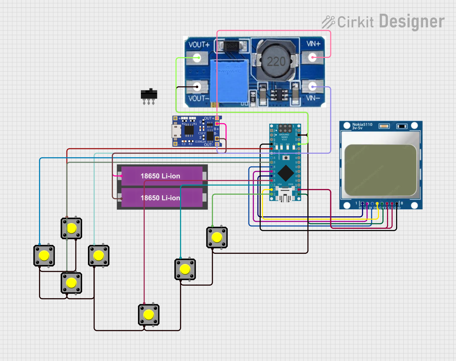
Example: Using TP5100 with Arduino UNO
The TP5100 can be used to power an Arduino UNO or charge a battery in an Arduino-based project. Below is an example of how to monitor the charging status using the CHG_OK pin:
// Example: Monitor TP5100 charging status with Arduino UNO

const int chgOkPin = 2; // CHG_OK pin connected to Arduino digital pin 2
const int ledPin = 13;  // Built-in LED on Arduino

void setup() {
  pinMode(chgOkPin, INPUT); // Set CHG_OK pin as input
  pinMode(ledPin, OUTPUT);  // Set LED pin as output
  Serial.begin(9600);       // Initialize serial communication
}

void loop() {
  int chargingStatus = digitalRead(chgOkPin); // Read CHG_OK pin status

  if (chargingStatus == LOW) {
    // Charging in progress
    digitalWrite(ledPin, HIGH); // Turn on LED
    Serial.println("Battery is charging...");
  } else {
    // Charging complete
    digitalWrite(ledPin, LOW);  // Turn off LED
    Serial.println("Charging complete.");
  }

  delay(1000); // Wait for 1 second before checking again
}
Troubleshooting and FAQs
Common Issues and Solutions
No Output Voltage
- Cause: The EN pin is not properly configured.
- Solution: Ensure the EN pin is pulled high to enable the regulator.
Overheating
- Cause: Insufficient heat dissipation or excessive load current.
- Solution: Add a heat sink or improve PCB thermal design. Reduce the load current if possible.
Battery Not Charging
- Cause: Incorrect battery connection or incompatible battery type.
- Solution: Verify the battery connection and ensure the battery is a compatible lithium-ion type.
Unstable Output Voltage
- Cause: Missing or insufficient input/output capacitors.
- Solution: Add low-ESR capacitors (e.g., 10µF at VIN and 22µF at VOUT).
FAQs
Q1: Can the TP5100 charge other types of batteries?
A1: No, the TP5100 is specifically designed for lithium-ion batteries. Using it with other battery chemistries may result in improper charging or damage.
Q2: What happens if the input voltage exceeds 18V?
A2: The TP5100 may be damaged if the input voltage exceeds its maximum rating. Always ensure the input voltage is within the specified range.
Q3: Can I leave the TS pin unconnected?
A3: Yes, but it is recommended to connect an NTC thermistor for battery temperature monitoring to enhance safety.
Q4: How do I know when the battery is fully charged?
A4: The CHG_OK pin will go high when the battery is fully charged. You can use this pin to drive an LED or interface with a microcontroller.