How to Use DC Jack Power Step down: Examples, Pinouts, and Specs
Introduction
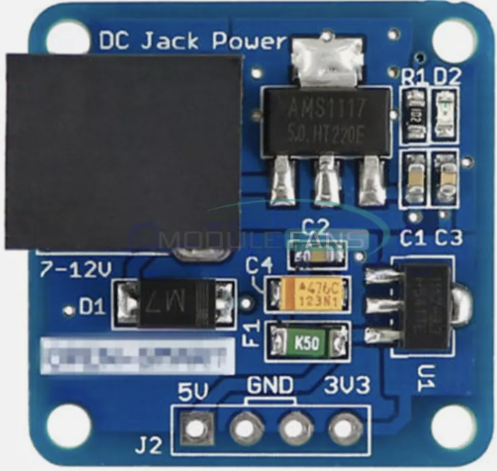
The DC Jack Power Step Down module is a versatile electronic component designed to step down a higher DC input voltage to a lower, regulated output voltage. It is commonly used in projects requiring a stable power supply for microcontrollers, sensors, and other low-voltage devices. The module typically features a DC barrel jack input, making it easy to connect to standard DC power adapters.
Explore Projects Built with DC Jack Power Step down


Explore Projects Built with DC Jack Power Step down
Common Applications and Use Cases
- Powering microcontrollers like Arduino, Raspberry Pi, or ESP32.
- Supplying regulated voltage to sensors, motors, and other peripherals.
- Prototyping circuits that require a stable DC voltage.
- Converting higher voltage sources (e.g., 12V or 9V) to 5V or 3.3V for low-power devices.
Technical Specifications
Below are the key technical details for the Generic DC Jack Power Step Down module:
| Parameter | Value |
|---|---|
| Input Voltage Range | 6V to 24V DC |
| Output Voltage | Adjustable (commonly 5V or 3.3V) |
| Maximum Output Current | 1A (varies by model) |
| Efficiency | Up to 90% |
| Dimensions | ~25mm x 20mm x 10mm |
| Operating Temperature | -40°C to +85°C |
Pin Configuration and Descriptions
| Pin/Connector | Description |
|---|---|
| DC Jack Input | Connects to a DC power source (e.g., 12V adapter). |
| VOUT (+) | Positive output voltage terminal. |
| GND (-) | Ground terminal for the output. |
| Adjustment Potentiometer | Used to fine-tune the output voltage. |
Usage Instructions
How to Use the Component in a Circuit
Connect the Input Voltage:
- Plug a DC power adapter (6V to 24V) into the DC jack input.
- Ensure the input voltage is within the specified range to avoid damage.
Adjust the Output Voltage:
- Use a small screwdriver to turn the adjustment potentiometer.
- Measure the output voltage using a multimeter and set it to the desired level (e.g., 5V or 3.3V).
Connect the Load:
- Attach the device or circuit to the VOUT (+) and GND (-) terminals.
- Ensure the load does not exceed the maximum output current rating.
Verify Connections:
- Double-check all connections before powering the module.
- Turn on the power source and confirm the output voltage is stable.
Important Considerations and Best Practices
- Heat Dissipation: If the module is used near its maximum current rating, ensure proper ventilation or add a heatsink to prevent overheating.
- Polarity Protection: Verify the polarity of the input voltage to avoid damaging the module.
- Output Filtering: For sensitive circuits, consider adding a capacitor (e.g., 100µF) across the output terminals to reduce noise.
- Arduino Compatibility: The module can be used to power an Arduino UNO by connecting the output to the Arduino's VIN and GND pins.
Example: Using with Arduino UNO
Below is an example of how to use the DC Jack Power Step Down module to power an Arduino UNO:
- Set the output voltage of the module to 9V using the potentiometer.
- Connect the module's VOUT (+) to the Arduino's VIN pin.
- Connect the module's GND (-) to the Arduino's GND pin.
// Example Arduino code to blink an LED
// This assumes the Arduino UNO is powered via the DC Jack Power Step Down module

const int ledPin = 13; // Built-in LED pin on Arduino UNO

void setup() {
  pinMode(ledPin, OUTPUT); // Set the LED pin as an output
}

void loop() {
  digitalWrite(ledPin, HIGH); // Turn the LED on
  delay(1000);                // Wait for 1 second
  digitalWrite(ledPin, LOW);  // Turn the LED off
  delay(1000);                // Wait for 1 second
}
Troubleshooting and FAQs
Common Issues and Solutions
No Output Voltage:
- Cause: Input voltage is not connected or is below the minimum required.
- Solution: Verify the input voltage is within the 6V to 24V range and check connections.
Output Voltage is Incorrect:
- Cause: Potentiometer is not adjusted correctly.
- Solution: Use a multimeter to measure the output and adjust the potentiometer.
Module Overheats:
- Cause: Load exceeds the maximum current rating.
- Solution: Reduce the load or add a heatsink for better heat dissipation.
Noise or Voltage Fluctuations:
- Cause: Insufficient filtering on the output.
- Solution: Add a capacitor (e.g., 100µF) across the output terminals.
FAQs
Q: Can I use this module to power a Raspberry Pi?
A: Yes, but ensure the output voltage is set to 5V and the current rating meets the Raspberry Pi's requirements.
Q: Is the module protected against reverse polarity?
A: Most generic modules do not have built-in reverse polarity protection. Always double-check the input connections.
Q: Can I use this module with a battery as the input source?
A: Yes, as long as the battery voltage is within the 6V to 24V range.
Q: How do I know if the module is overloaded?
A: If the module overheats or the output voltage drops significantly, it may be overloaded. Reduce the load to resolve the issue.