Cirkit Designer Logo
Cirkit Designer
Your all-in-one circuit design IDE
Home / 
Component Documentation

How to Use IRF520 MOSFET Driver Module: Examples, Pinouts, and Specs

Image of IRF520 MOSFET Driver Module
Cirkit Designer LogoDesign with IRF520 MOSFET Driver Module in Cirkit Designer

Introduction

The IRF520 MOSFET Driver Module is a versatile electronic component designed to control high-power devices using low-power signals. It leverages the IRF520 N-channel MOSFET, which is known for its efficiency in switching and amplification. This module is commonly used in applications such as motor control, LED dimming, and driving high-current loads in automation systems. Its compact design and ease of use make it a popular choice for hobbyists and professionals alike.

Explore Projects Built with IRF520 MOSFET Driver Module

Use Cirkit Designer to design, explore, and prototype these projects online. Some projects support real-time simulation. Click "Open Project" to start designing instantly!
Pixhawk-Controlled Solenoid Driver with Voltage Regulation
Image of solenoid control circuit: A project utilizing IRF520 MOSFET Driver Module in a practical application
This circuit uses an LM393 comparator to drive an IRFZ44N MOSFET based on the comparison between two input signals from a pixhawk 2.4.8 flight controller. The MOSFET switches a solenoid, with a diode for back EMF protection, and the system is powered by a Lipo battery with voltage regulation provided by a step-up boost converter and a step-down voltage regulator to ensure stable operation. A resistor is connected to the gate of the MOSFET for proper biasing.
Cirkit Designer LogoOpen Project in Cirkit Designer
Battery-Powered LM393-Based Voltage Comparator Circuit with MOSFET Control
Image of cut off charger: A project utilizing IRF520 MOSFET Driver Module in a practical application
This circuit is a power regulation and control system that uses an LM393 comparator to monitor voltage levels and control a MOSFET (IRFZ44N) for switching. It is powered by a 12V battery and a USB power source, and includes various resistors and capacitors for filtering and stabilization.
Cirkit Designer LogoOpen Project in Cirkit Designer
ESP8266-Controlled Wireless EV Charging System with RFID Authentication
Image of Minor Project: A project utilizing IRF520 MOSFET Driver Module in a practical application
This circuit appears to be a wireless charging system with RFID access control, powered by an AC supply that is rectified and regulated. It includes an ESP8266 microcontroller for managing the charging process and displaying status information on an OLED display. The RFID-RC522 module is used to authorize the charging process, and a MOSFET is likely used to control the power to the charging coil.
Cirkit Designer LogoOpen Project in Cirkit Designer
Dual Motor Control Circuit with LED Indicator and Adjustable Speed
Image of Simple Drone: A project utilizing IRF520 MOSFET Driver Module in a practical application
This circuit is designed to control the speed and direction of coreless motors using MOSFETs, with a potentiometer providing adjustable speed control for one direction. A rocker switch enables power control, and a red LED serves as a power indicator. Diodes are included for motor back-EMF protection.
Cirkit Designer LogoOpen Project in Cirkit Designer

Explore Projects Built with IRF520 MOSFET Driver Module

Use Cirkit Designer to design, explore, and prototype these projects online. Some projects support real-time simulation. Click "Open Project" to start designing instantly!
Image of solenoid control circuit: A project utilizing IRF520 MOSFET Driver Module in a practical application
Pixhawk-Controlled Solenoid Driver with Voltage Regulation
This circuit uses an LM393 comparator to drive an IRFZ44N MOSFET based on the comparison between two input signals from a pixhawk 2.4.8 flight controller. The MOSFET switches a solenoid, with a diode for back EMF protection, and the system is powered by a Lipo battery with voltage regulation provided by a step-up boost converter and a step-down voltage regulator to ensure stable operation. A resistor is connected to the gate of the MOSFET for proper biasing.
Cirkit Designer LogoOpen Project in Cirkit Designer
Image of cut off charger: A project utilizing IRF520 MOSFET Driver Module in a practical application
Battery-Powered LM393-Based Voltage Comparator Circuit with MOSFET Control
This circuit is a power regulation and control system that uses an LM393 comparator to monitor voltage levels and control a MOSFET (IRFZ44N) for switching. It is powered by a 12V battery and a USB power source, and includes various resistors and capacitors for filtering and stabilization.
Cirkit Designer LogoOpen Project in Cirkit Designer
Image of Minor Project: A project utilizing IRF520 MOSFET Driver Module in a practical application
ESP8266-Controlled Wireless EV Charging System with RFID Authentication
This circuit appears to be a wireless charging system with RFID access control, powered by an AC supply that is rectified and regulated. It includes an ESP8266 microcontroller for managing the charging process and displaying status information on an OLED display. The RFID-RC522 module is used to authorize the charging process, and a MOSFET is likely used to control the power to the charging coil.
Cirkit Designer LogoOpen Project in Cirkit Designer
Image of Simple Drone: A project utilizing IRF520 MOSFET Driver Module in a practical application
Dual Motor Control Circuit with LED Indicator and Adjustable Speed
This circuit is designed to control the speed and direction of coreless motors using MOSFETs, with a potentiometer providing adjustable speed control for one direction. A rocker switch enables power control, and a red LED serves as a power indicator. Diodes are included for motor back-EMF protection.
Cirkit Designer LogoOpen Project in Cirkit Designer

Common Applications:

  • Driving DC motors
  • Controlling high-power LEDs
  • Switching solenoids and relays
  • General-purpose high-current load control
  • PWM (Pulse Width Modulation) applications

Technical Specifications

Key Technical Details:

  • MOSFET Type: IRF520 N-channel MOSFET
  • Input Voltage (Logic Level): 3.3V to 5V
  • Load Voltage: Up to 24V DC
  • Load Current: Up to 5A (with proper heat dissipation)
  • Trigger Current: 15mA (typical)
  • On-Resistance (RDS(on)): 0.27Ω (at 10V gate drive)
  • Module Dimensions: 33mm x 24mm x 15mm (approx.)

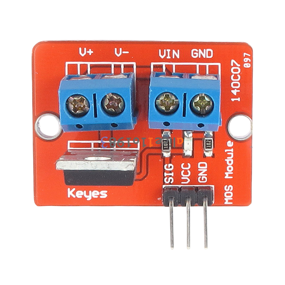
Pin Configuration and Descriptions:

The IRF520 MOSFET Driver Module typically has a 3-pin input interface and a 2-pin output interface. Below is the pinout description:

Input Pins:

Pin Name Description
VCC Power supply for the module (3.3V-5V)
GND Ground connection
SIG Signal input to control the MOSFET

Output Pins:

Pin Name Description
V+ Positive terminal for the load
V- Negative terminal for the load

Usage Instructions

How to Use the IRF520 MOSFET Driver Module:

  1. Connect the Power Supply:

    • Connect the VCC pin to a 3.3V or 5V power source.
    • Connect the GND pin to the ground of your circuit.
  2. Connect the Load:

    • Attach the positive terminal of your load to the V+ pin.
    • Connect the negative terminal of your load to the V- pin.
  3. Control the Module:

    • Use a microcontroller (e.g., Arduino UNO) or other logic-level signal source to send a control signal to the SIG pin.
    • A HIGH signal (3.3V or 5V) will turn the MOSFET ON, allowing current to flow through the load.
    • A LOW signal (0V) will turn the MOSFET OFF, stopping current flow.
  4. Ensure Proper Heat Dissipation:

    • For high-current loads, attach a heatsink to the IRF520 MOSFET to prevent overheating.

Example Arduino Code:

Below is an example of how to use the IRF520 MOSFET Driver Module with an Arduino UNO to control an LED:

// Define the pin connected to the SIG pin of the IRF520 module
const int mosfetPin = 9;

void setup() {
  // Set the MOSFET control pin as an output
  pinMode(mosfetPin, OUTPUT);
}

void loop() {
  // Turn the MOSFET ON (LED ON)
  digitalWrite(mosfetPin, HIGH);
  delay(1000); // Keep the LED ON for 1 second

  // Turn the MOSFET OFF (LED OFF)
  digitalWrite(mosfetPin, LOW);
  delay(1000); // Keep the LED OFF for 1 second
}

Important Considerations:

  • Voltage Compatibility: Ensure the load voltage does not exceed 24V DC.
  • Current Handling: Do not exceed the maximum current rating of 5A without proper heat dissipation.
  • Signal Voltage: The SIG pin is compatible with 3.3V and 5V logic levels, making it suitable for most microcontrollers.
  • Inductive Loads: When driving inductive loads (e.g., motors, solenoids), use a flyback diode across the load to protect the MOSFET from voltage spikes.

Troubleshooting and FAQs

Common Issues and Solutions:

  1. The load does not turn ON:

    • Verify that the SIG pin is receiving a HIGH signal (3.3V or 5V).
    • Check the connections to ensure the load is properly connected to the V+ and V- pins.
    • Ensure the power supply voltage and current are sufficient for the load.
  2. The MOSFET overheats:

    • Attach a heatsink to the IRF520 MOSFET for better heat dissipation.
    • Reduce the load current if possible.
  3. The module does not respond to the control signal:

    • Confirm that the VCC and GND pins are correctly connected to the power supply.
    • Check the SIG pin connection and ensure the microcontroller is functioning properly.
  4. The load flickers or behaves erratically:

    • Ensure the power supply is stable and capable of handling the load's current requirements.
    • For PWM applications, verify that the PWM frequency is appropriate for the load.

FAQs:

Q: Can I use the IRF520 module with a 12V motor?
A: Yes, the IRF520 module can handle up to 24V DC, so it is suitable for a 12V motor. Ensure the motor's current does not exceed 5A.

Q: Is the IRF520 module compatible with 3.3V logic?
A: Yes, the SIG pin can accept both 3.3V and 5V logic levels, making it compatible with most microcontrollers.

Q: Do I need a heatsink for low-current applications?
A: No, a heatsink is generally not required for low-current applications (e.g., under 1A). However, for higher currents, a heatsink is recommended.

Q: Can I use this module for AC loads?
A: No, the IRF520 module is designed for DC loads only. It cannot be used to control AC devices.

By following this documentation, you can effectively use the IRF520 MOSFET Driver Module in your electronic projects.