How to Use OV7670_Fifo Camera: Examples, Pinouts, and Specs
Introduction
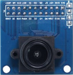
The OV7670_Fifo Camera, manufactured by OmniVision, is a low-cost image sensor module designed for capturing video and still images. It features a built-in FIFO (First In, First Out) buffer, which temporarily stores image data, enabling smoother and more efficient data transfer to microcontrollers or processors. This makes it an excellent choice for applications requiring image processing in embedded systems.
Explore Projects Built with OV7670_Fifo Camera
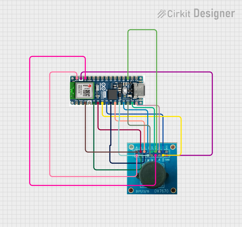
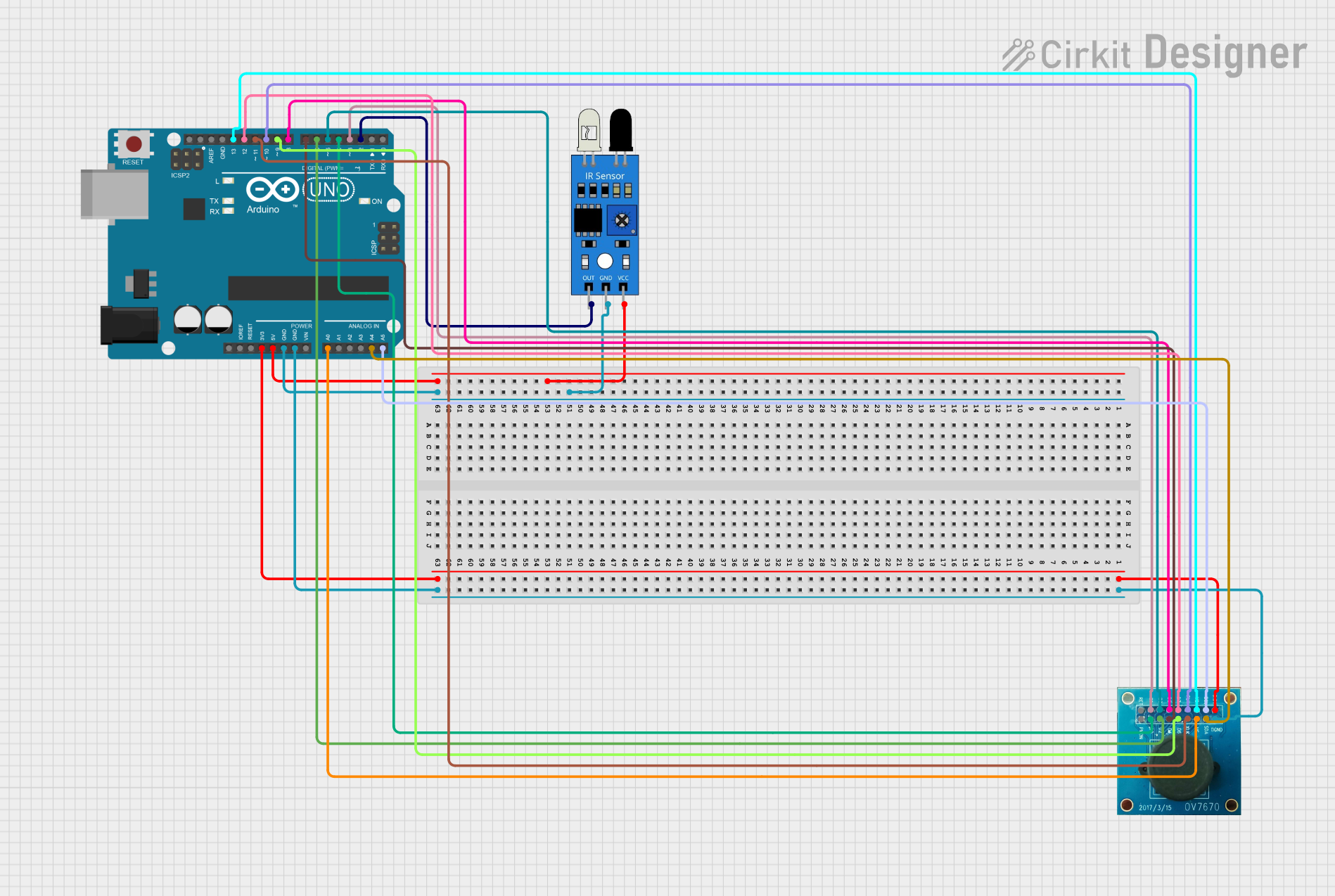
Explore Projects Built with OV7670_Fifo Camera
Common Applications and Use Cases
- Robotics: Object detection, line following, and visual navigation.
- Embedded Systems: Image capture and processing for IoT devices.
- Security Systems: Low-cost surveillance cameras.
- Educational Projects: Learning image processing and computer vision concepts.
- DIY Electronics: Custom camera-based projects.
Technical Specifications
Key Technical Details
| Parameter | Value |
|---|---|
| Manufacturer | OmniVision |
| Image Sensor Type | CMOS |
| Resolution | VGA (640x480) |
| Pixel Size | 3.6 µm x 3.6 µm |
| Maximum Frame Rate | 30 fps (frames per second) |
| Supply Voltage | 3.3V (core), 2.5V to 3.0V (I/O) |
| Operating Temperature | -30°C to +70°C |
| Communication Interface | SCCB (Serial Camera Control Bus) |
| FIFO Buffer Size | 3Mbit |
| Lens Type | Fixed focus |
Pin Configuration and Descriptions
The OV7670_Fifo Camera module typically has a 20-pin interface. Below is the pinout and description:
| Pin Number | Pin Name | Description |
|---|---|---|
| 1 | GND | Ground connection |
| 2 | VCC | Power supply (3.3V) |
| 3 | SCL | SCCB clock line |
| 4 | SDA | SCCB data line |
| 5 | VSYNC | Vertical synchronization signal |
| 6 | HREF | Horizontal reference signal |
| 7 | PCLK | Pixel clock output |
| 8 | XCLK | External clock input |
| 9-16 | D0-D7 | Data output pins (8-bit parallel data) |
| 17 | RESET | Active-low reset signal |
| 18 | OE | Output enable (active low) |
| 19 | WEN | Write enable for FIFO |
| 20 | RCLK | Read clock for FIFO |
Usage Instructions
How to Use the OV7670_Fifo Camera in a Circuit
- Power Supply: Connect the VCC pin to a 3.3V power source and GND to ground.
- Clock Signal: Provide an external clock signal (XCLK) to the module. A common frequency is 24 MHz.
- SCCB Communication: Use the SCL and SDA pins to configure the camera settings via the SCCB protocol. This is similar to I2C communication.
- FIFO Buffer: Use the WEN and RCLK pins to control the FIFO buffer for reading image data.
- Data Output: Connect the D0-D7 pins to the microcontroller or processor to receive the image data in an 8-bit parallel format.
- Synchronization: Use the VSYNC, HREF, and PCLK signals to synchronize the data transfer.
Important Considerations and Best Practices
- Voltage Levels: Ensure that the I/O voltage levels of your microcontroller are compatible with the OV7670 (2.5V to 3.0V). Use level shifters if necessary.
- Clock Source: A stable clock source is critical for proper operation. Use a crystal oscillator or a microcontroller-generated clock.
- FIFO Management: Properly manage the FIFO buffer to avoid data loss or corruption.
- Lens Adjustment: The fixed-focus lens may need manual adjustment for optimal image clarity.
- Decoupling Capacitors: Place decoupling capacitors near the power pins to reduce noise and improve stability.
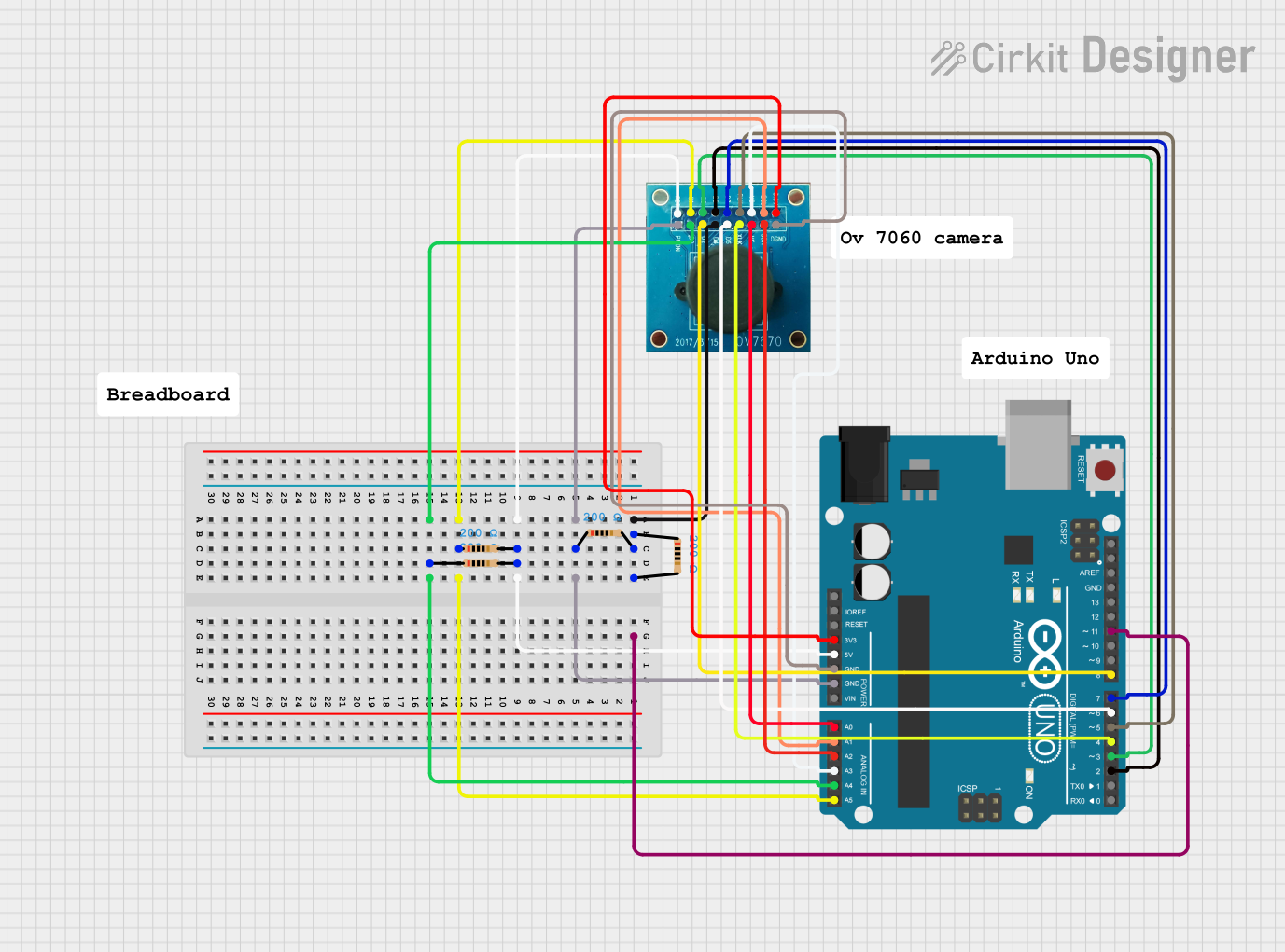
Example: Connecting to an Arduino UNO
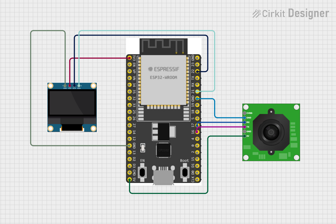
Below is an example of how to connect and use the OV7670_Fifo Camera with an Arduino UNO. Note that the Arduino UNO may have limited processing power for advanced image processing tasks.
Wiring Diagram
| OV7670 Pin | Arduino Pin |
|---|---|
| VCC | 3.3V |
| GND | GND |
| SCL | A5 |
| SDA | A4 |
| VSYNC | Digital Pin 2 |
| HREF | Digital Pin 3 |
| PCLK | Digital Pin 4 |
| XCLK | Digital Pin 9 (PWM) |
| D0-D7 | Digital Pins 5-12 |
Sample Code
#include <Wire.h>

// Define OV7670 SCCB address
#define OV7670_ADDR 0x42

// Function to write a register value to the OV7670
void writeRegister(uint8_t reg, uint8_t value) {
  Wire.beginTransmission(OV7670_ADDR >> 1); // Shift address for 7-bit format
  Wire.write(reg);                          // Register address
  Wire.write(value);                        // Value to write
  Wire.endTransmission();
}

void setup() {
  Wire.begin(); // Initialize I2C communication
  Serial.begin(9600); // Initialize serial communication for debugging

  // Example: Set the OV7670 to VGA resolution
  writeRegister(0x12, 0x00); // COM7 register: Reset and set VGA mode

  Serial.println("OV7670 initialized.");
}

void loop() {
  // Add code to read image data from the FIFO and process it
}
Troubleshooting and FAQs
Common Issues and Solutions
No Image Output:
- Ensure the XCLK signal is stable and within the required frequency range.
- Verify the SCCB communication by checking the wiring and pull-up resistors on the SCL and SDA lines.
Corrupted Image Data:
- Check the synchronization signals (VSYNC, HREF, PCLK) for proper timing.
- Ensure the FIFO buffer is being read and managed correctly.
Camera Not Detected:
- Verify the SCCB address (default is 0x42).
- Check for loose or incorrect connections.
Blurry Images:
- Adjust the fixed-focus lens for better clarity.
- Ensure the object is within the focus range of the lens.
FAQs
Q: Can the OV7670_Fifo Camera capture color images?
A: Yes, the OV7670 supports RGB565 and YUV422 color formats.
Q: What is the maximum resolution of the OV7670?
A: The maximum resolution is VGA (640x480).
Q: Can I use the OV7670 with a 5V microcontroller?
A: Yes, but you must use level shifters to ensure the I/O voltage levels are compatible.
Q: Is the FIFO buffer necessary for operation?
A: The FIFO buffer simplifies data transfer and is highly recommended for microcontrollers with limited processing power.