
How to Use LSM6DS33 3D Accelerometer: Examples, Pinouts, and Specs
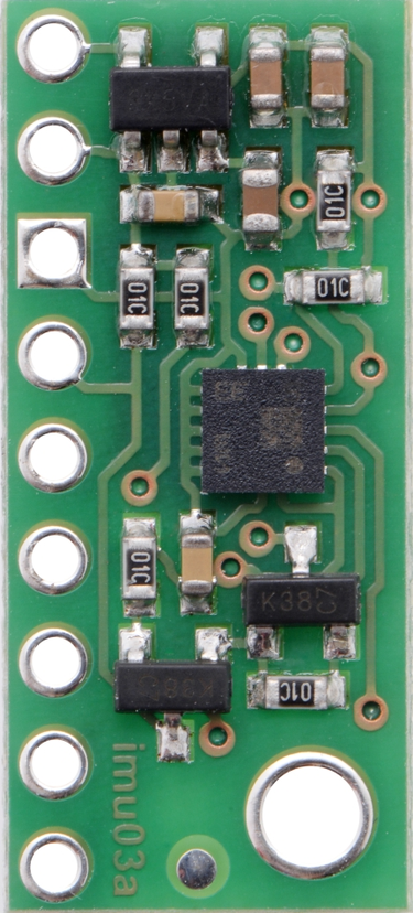
 Design with LSM6DS33 3D Accelerometer in Cirkit Designer
Introduction
The LSM6DS33 is a high-performance 3D accelerometer and 3D gyroscope sensor manufactured by Pololu. It is designed to provide precise motion sensing capabilities with a digital output. This sensor is widely used in applications such as smartphones, wearables, gaming devices, and IoT systems for detecting orientation, motion, and acceleration. Its compact size and low power consumption make it ideal for portable and battery-powered devices.
Explore Projects Built with LSM6DS33 3D Accelerometer
 Open Project in Cirkit Designer
 Open Project in Cirkit Designer
 Open Project in Cirkit Designer
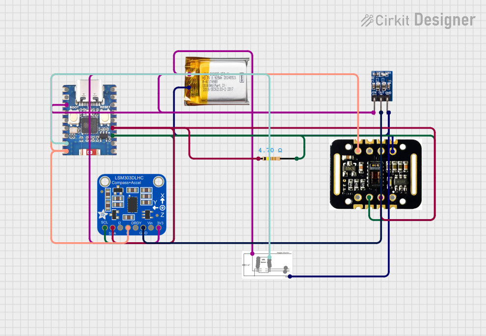 Open Project in Cirkit Designer
Explore Projects Built with LSM6DS33 3D Accelerometer
Open Project in Cirkit DesignerOpen Project in Cirkit DesignerOpen Project in Cirkit DesignerOpen Project in Cirkit DesignerCommon Applications
- Motion tracking in smartphones and tablets
- Wearable fitness trackers and health monitoring devices
- Robotics and drone stabilization
- Gaming controllers for motion-based input
- IoT devices for gesture recognition and activity monitoring
Technical Specifications
Key Technical Details
| Parameter | Value |
|---|---|
| Manufacturer | Pololu |
| Part ID | LSM6DS33 |
| Sensor Type | 3D Accelerometer and 3D Gyroscope |
| Communication Interface | I²C, SPI |
| Operating Voltage | 1.71 V to 3.6 V |
| Accelerometer Range | ±2 g, ±4 g, ±8 g, ±16 g |
| Gyroscope Range | ±125 dps, ±245 dps, ±500 dps, ±1000 dps, ±2000 dps |
| Output Data Rate (ODR) | Up to 6.66 kHz |
| Operating Temperature Range | -40°C to +85°C |
| Power Consumption | 0.9 mA (accelerometer + gyroscope active) |
| Package Size | 2.5 mm x 3.0 mm x 0.83 mm |
Pin Configuration and Descriptions
The LSM6DS33 is typically available on breakout boards for easier integration. Below is the pin configuration for a common breakout board:
| Pin Name | Description |
|---|---|
| VIN | Power supply input (1.71 V to 3.6 V). Can be connected to 3.3 V or 5 V. |
| GND | Ground connection. |
| SCL | I²C clock line or SPI clock line. |
| SDA | I²C data line or SPI data input/output. |
| CS | Chip select for SPI communication (active low). |
| INT1 | Interrupt 1 output. Can be configured for various events. |
| INT2 | Interrupt 2 output. Can be configured for various events. |
Usage Instructions
How to Use the LSM6DS33 in a Circuit
- Power Supply: Connect the VIN pin to a 3.3 V or 5 V power source and GND to ground.
- Communication Interface: Choose between I²C or SPI for communication:
- For I²C, connect the SCL and SDA pins to the corresponding I²C lines on your microcontroller.
- For SPI, connect the SCL (SPI clock), SDA (SPI data), and CS (chip select) pins to the appropriate SPI lines.
- Interrupts: Optionally, connect INT1 and/or INT2 to your microcontroller for event-driven applications.
- Pull-Up Resistors: If using I²C, ensure pull-up resistors (typically 4.7 kΩ) are present on the SCL and SDA lines.
Important Considerations and Best Practices
- Voltage Compatibility: Ensure the operating voltage of the LSM6DS33 matches your system. Use a level shifter if interfacing with a 5 V microcontroller.
- Bypass Capacitor: Place a 0.1 µF capacitor close to the VIN pin for power supply stability.
- Mounting Orientation: Properly align the sensor on your PCB to match the desired axes of measurement.
- Configuration: Use the sensor's registers to configure the accelerometer and gyroscope ranges, output data rates, and interrupt settings.
Example Code for Arduino UNO
Below is an example of how to interface the LSM6DS33 with an Arduino UNO using the I²C protocol:
#include <Wire.h>

// LSM6DS33 I2C address
#define LSM6DS33_ADDR 0x6B

// Register addresses
#define CTRL1_XL 0x10  // Accelerometer control register
#define CTRL2_G  0x11  // Gyroscope control register
#define OUTX_L_XL 0x28 // Accelerometer X-axis low byte
#define OUTX_H_XL 0x29 // Accelerometer X-axis high byte

void setup() {
  Wire.begin(); // Initialize I2C communication
  Serial.begin(9600); // Initialize serial communication for debugging

  // Configure accelerometer (±2g, 104 Hz ODR)
  writeRegister(CTRL1_XL, 0x40);

  // Configure gyroscope (±245 dps, 104 Hz ODR)
  writeRegister(CTRL2_G, 0x40);

  Serial.println("LSM6DS33 initialized.");
}

void loop() {
  int16_t accelX = read16BitRegister(OUTX_L_XL, OUTX_H_XL);

  // Convert raw data to g (assuming ±2g range)
  float accelX_g = accelX * 0.061 / 1000; // 0.061 mg/LSB for ±2g range

  Serial.print("Acceleration X: ");
  Serial.print(accelX_g);
  Serial.println(" g");

  delay(500); // Delay for readability
}

// Function to write a value to a register
void writeRegister(uint8_t reg, uint8_t value) {
  Wire.beginTransmission(LSM6DS33_ADDR);
  Wire.write(reg);
  Wire.write(value);
  Wire.endTransmission();
}

// Function to read a 16-bit value from two consecutive registers
int16_t read16BitRegister(uint8_t regL, uint8_t regH) {
  Wire.beginTransmission(LSM6DS33_ADDR);
  Wire.write(regL);
  Wire.endTransmission(false);
  Wire.requestFrom(LSM6DS33_ADDR, 2);

  uint8_t lowByte = Wire.read();
  uint8_t highByte = Wire.read();

  return (int16_t)((highByte << 8) | lowByte);
}
Troubleshooting and FAQs
Common Issues
No Communication with the Sensor
- Ensure the correct I²C address (0x6B) is being used.
- Verify the wiring connections, especially SCL and SDA lines.
- Check for proper pull-up resistors on the I²C lines.
Incorrect or No Data Output
- Confirm that the sensor is properly configured (e.g., accelerometer and gyroscope ranges).
- Verify the power supply voltage is within the specified range (1.71 V to 3.6 V).
- Ensure the sensor is not in sleep mode.
High Noise in Measurements
- Use proper PCB layout techniques to minimize noise.
- Enable the sensor's built-in filtering features via configuration registers.
FAQs
Q: Can the LSM6DS33 be used with a 5 V microcontroller?
A: Yes, but you may need a level shifter for the I²C or SPI lines if the microcontroller operates at 5 V logic levels.
Q: How do I change the accelerometer or gyroscope range?
A: Modify the appropriate control registers (e.g., CTRL1_XL for the accelerometer and CTRL2_G for the gyroscope) to set the desired range.
Q: What is the maximum sampling rate of the LSM6DS33?
A: The sensor supports an output data rate (ODR) of up to 6.66 kHz for both the accelerometer and gyroscope.
This concludes the documentation for the LSM6DS33 3D Accelerometer. For further details, refer to the official datasheet provided by Pololu.