How to Use KEYPAD 4X3: Examples, Pinouts, and Specs
Introduction
The KEYPAD 4X3 by HAQIMNI (Part ID: KEYPAD) is a 4x3 matrix keypad featuring 12 keys arranged in 4 rows and 3 columns. This component is widely used for user input in electronic devices, such as security systems, calculators, and embedded systems. Its compact design and ease of integration make it a popular choice for projects requiring a simple and reliable input interface.
Explore Projects Built with KEYPAD 4X3


Explore Projects Built with KEYPAD 4X3
Common Applications
- Security systems (e.g., password entry for door locks)
- Embedded systems requiring numeric or alphanumeric input
- Home automation control panels
- Calculators and handheld devices
- Menu navigation in microcontroller-based projects
Technical Specifications
Key Specifications
| Parameter | Value |
|---|---|
| Manufacturer | HAQIMNI |
| Part ID | KEYPAD |
| Key Layout | 4 rows x 3 columns |
| Number of Keys | 12 |
| Operating Voltage | 3.3V to 5V |
| Maximum Current | 10mA |
| Contact Resistance | < 200Ω |
| Keypad Dimensions | 70mm x 50mm x 10mm |
| Connector Type | 7-pin header |
| Operating Temperature | -20°C to 70°C |
Pin Configuration
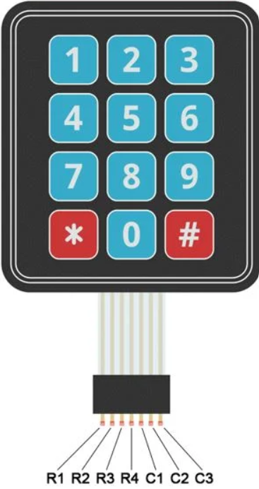
The KEYPAD 4X3 has a 7-pin interface, with 4 pins for rows and 3 pins for columns. The table below describes the pinout:
| Pin Number | Pin Name | Description |
|---|---|---|
| 1 | ROW1 | Row 1 connection |
| 2 | ROW2 | Row 2 connection |
| 3 | ROW3 | Row 3 connection |
| 4 | ROW4 | Row 4 connection |
| 5 | COL1 | Column 1 connection |
| 6 | COL2 | Column 2 connection |
| 7 | COL3 | Column 3 connection |
Usage Instructions
How to Use the KEYPAD 4X3 in a Circuit
Connect the Keypad to a Microcontroller:
- Use the 7-pin header to connect the keypad to the microcontroller.
- Assign the row pins (ROW1 to ROW4) to digital input/output pins on the microcontroller.
- Similarly, assign the column pins (COL1 to COL3) to digital input/output pins.
Scan the Keypad Matrix:
- To detect key presses, implement a scanning algorithm.
- Set one row pin HIGH at a time while keeping the others LOW.
- Check the column pins for a HIGH signal to determine which key is pressed.
Debounce the Keys:
- Use software or hardware debouncing to eliminate false keypresses caused by mechanical bouncing.
Power Requirements:
- Ensure the keypad is powered within its operating voltage range (3.3V to 5V).
- Avoid exceeding the maximum current rating of 10mA.
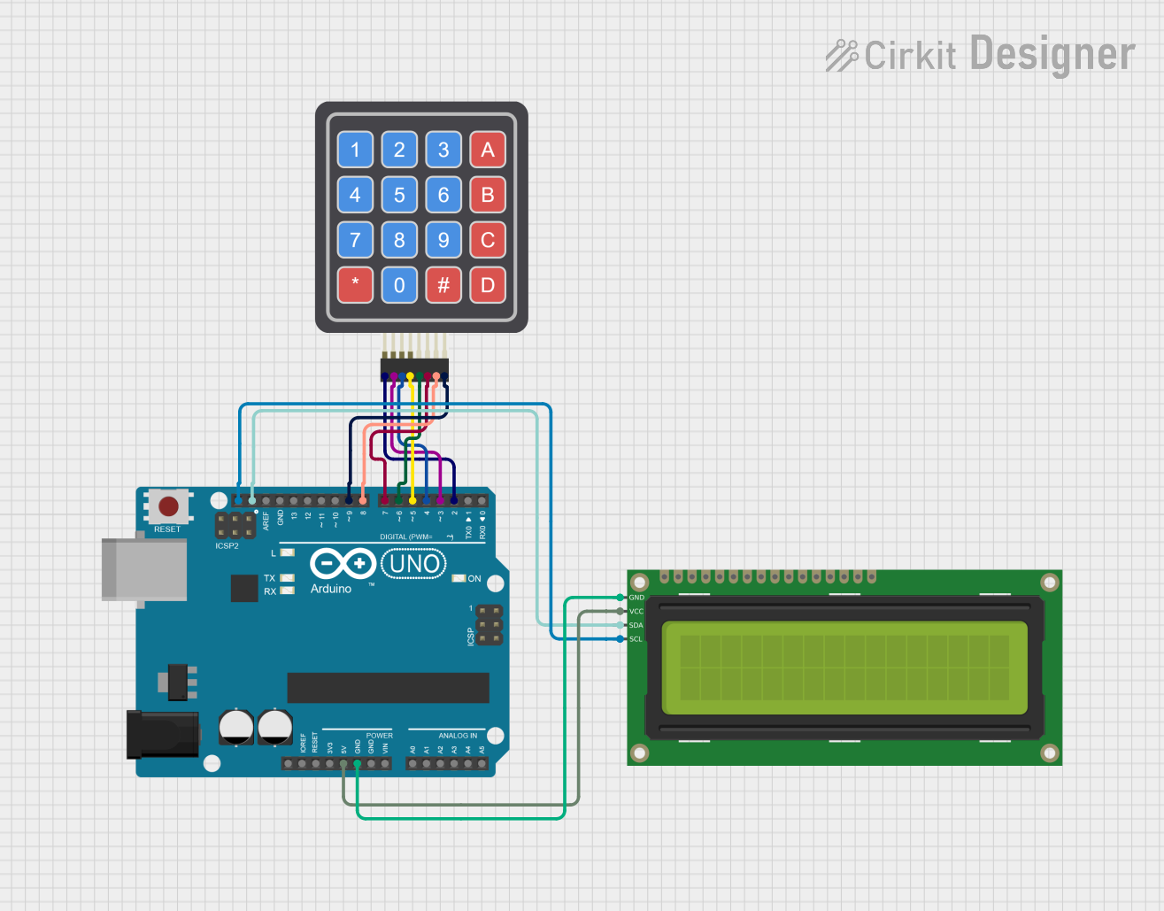
Example: Using KEYPAD 4X3 with Arduino UNO
Below is an example of how to interface the KEYPAD 4X3 with an Arduino UNO using the Keypad library.
Circuit Connections
| Keypad Pin | Arduino Pin |
|---|---|
| ROW1 | D2 |
| ROW2 | D3 |
| ROW3 | D4 |
| ROW4 | D5 |
| COL1 | D6 |
| COL2 | D7 |
| COL3 | D8 |
Arduino Code
#include <Keypad.h>

// Define the rows and columns of the keypad
const byte ROWS = 4; // Four rows
const byte COLS = 3; // Three columns

// Define the keymap for the keypad
char keys[ROWS][COLS] = {
  {'1', '2', '3'},
  {'4', '5', '6'},
  {'7', '8', '9'},
  {'*', '0', '#'}
};

// Define the row and column pins connected to the Arduino
byte rowPins[ROWS] = {2, 3, 4, 5}; // Connect to ROW1, ROW2, ROW3, ROW4
byte colPins[COLS] = {6, 7, 8};    // Connect to COL1, COL2, COL3

// Create the Keypad object
Keypad keypad = Keypad(makeKeymap(keys), rowPins, colPins, ROWS, COLS);

void setup() {
  Serial.begin(9600); // Initialize serial communication
  Serial.println("Keypad Test: Press a key");
}

void loop() {
  char key = keypad.getKey(); // Get the key pressed

  if (key) {
    // If a key is pressed, print it to the Serial Monitor
    Serial.print("Key Pressed: ");
    Serial.println(key);
  }
}
Best Practices
- Use pull-down resistors on the row or column pins if necessary to avoid floating inputs.
- Avoid pressing multiple keys simultaneously, as this may cause ghosting or incorrect key detection.
- Use a stable power supply to ensure reliable operation.
Troubleshooting and FAQs
Common Issues and Solutions
| Issue | Possible Cause | Solution |
|---|---|---|
| No keypress detected | Incorrect wiring or loose connections | Verify all connections and pin mapping. |
| Multiple keys detected at once | Ghosting due to lack of diodes | Add diodes to the matrix or avoid simultaneous keypresses. |
| Unresponsive keypad | Voltage or current out of range | Ensure the keypad is powered within 3.3V to 5V. |
| Erratic keypress behavior | Mechanical bouncing | Implement software or hardware debouncing. |
FAQs
Can the KEYPAD 4X3 be used with 3.3V microcontrollers?
Yes, the keypad operates within a voltage range of 3.3V to 5V.How do I prevent ghosting in the keypad matrix?
Ghosting can be prevented by adding diodes to the matrix or by avoiding simultaneous keypresses.What is the lifespan of the keys?
The keys are rated for over 1 million presses under normal operating conditions.Can I use this keypad for alphanumeric input?
Yes, you can map the keys to alphanumeric characters in your software.
By following this documentation, you can effectively integrate the KEYPAD 4X3 into your projects and troubleshoot any issues that arise.