Cirkit Designer Logo
Cirkit Designer
Your all-in-one circuit design IDE
Home / 
Component Documentation

How to Use Gear Motor with integrated Encoder: Examples, Pinouts, and Specs

Image of Gear Motor with integrated Encoder
Cirkit Designer LogoDesign with Gear Motor with integrated Encoder in Cirkit Designer

Introduction

A gear motor with an integrated encoder by Naroote is a compact and efficient solution for precise motion control in various applications. This component combines a geared electric motor with a rotary encoder, providing both the mechanical power to drive a system and the capability to monitor and control the position, speed, or direction of the motor shaft. Common applications include robotics, automated machinery, conveyor systems, and any application where precise motor control is required.

Explore Projects Built with Gear Motor with integrated Encoder

Use Cirkit Designer to design, explore, and prototype these projects online. Some projects support real-time simulation. Click "Open Project" to start designing instantly!
Arduino-Controlled DC Motor with Encoder Feedback and Adjustable Speed
Image of gear motor: A project utilizing Gear Motor with integrated Encoder in a practical application
This circuit controls a gear motor with an integrated encoder using an L298N DC motor driver, which is interfaced with an Arduino Mega 2560 microcontroller. The motor's power is supplied by a 12V power source, which is also connected to an XL4015 DC Buck Step-down converter to provide a regulated 5V supply to the Arduino. The encoder outputs are connected to the Arduino for position or speed feedback, and the Arduino is programmed to manage the motor's speed and direction.
Cirkit Designer LogoOpen Project in Cirkit Designer
Arduino UNO Controlled Gear Motor and Servo System with Integrated Encoder
Image of circuit électrique global de la plateforme : A project utilizing Gear Motor with integrated Encoder in a practical application
This circuit controls a gear motor with an integrated encoder and a servo motor using an Arduino UNO. The Arduino reads encoder signals to measure the motor's speed and direction, and it can control the motor's speed and direction via a Cytron MD-10 motor driver. Additionally, the Arduino controls the position of a servo motor.
Cirkit Designer LogoOpen Project in Cirkit Designer
Arduino Mega 2560 and ESP32 Powered Autonomous Robot
Image of PID Line Following Robot (Breadboarded): A project utilizing Gear Motor with integrated Encoder in a practical application
This circuit is designed to control and monitor a pair of gear motors with integrated encoders, likely for a robotic or automated motion application. It uses an Arduino Mega 2560 for processing inputs and outputs, which include driving the motors via a dual TB6612FNG motor driver, reading from a QTRX-HD-07RC reflectance sensor array, and interfacing with an HC-SR04 ultrasonic sensor for distance measurement. Power management is handled by a combination of lithium battery charging and protection modules, a step-up boost converter, and a buck converter to regulate the supply voltage for the system.
Cirkit Designer LogoOpen Project in Cirkit Designer
Arduino-Controlled Robotic System with Servos, Ultrasonic Sensors, and Gear Motor
Image of integrated circuit: A project utilizing Gear Motor with integrated Encoder in a practical application
This circuit is designed to control a gear motor with an integrated encoder and a servo motor, using an Arduino UNO as the central microcontroller. It includes an L298N motor driver to drive the gear motor, and multiple HC-SR04 ultrasonic sensors for distance measurement. The circuit is powered by a 12V power supply, regulated down to 5V by an XL4015 DC-DC buck converter to power the Arduino and other 5V components.
Cirkit Designer LogoOpen Project in Cirkit Designer

Explore Projects Built with Gear Motor with integrated Encoder

Use Cirkit Designer to design, explore, and prototype these projects online. Some projects support real-time simulation. Click "Open Project" to start designing instantly!
Image of gear motor: A project utilizing Gear Motor with integrated Encoder in a practical application
Arduino-Controlled DC Motor with Encoder Feedback and Adjustable Speed
This circuit controls a gear motor with an integrated encoder using an L298N DC motor driver, which is interfaced with an Arduino Mega 2560 microcontroller. The motor's power is supplied by a 12V power source, which is also connected to an XL4015 DC Buck Step-down converter to provide a regulated 5V supply to the Arduino. The encoder outputs are connected to the Arduino for position or speed feedback, and the Arduino is programmed to manage the motor's speed and direction.
Cirkit Designer LogoOpen Project in Cirkit Designer
Image of circuit électrique global de la plateforme : A project utilizing Gear Motor with integrated Encoder in a practical application
Arduino UNO Controlled Gear Motor and Servo System with Integrated Encoder
This circuit controls a gear motor with an integrated encoder and a servo motor using an Arduino UNO. The Arduino reads encoder signals to measure the motor's speed and direction, and it can control the motor's speed and direction via a Cytron MD-10 motor driver. Additionally, the Arduino controls the position of a servo motor.
Cirkit Designer LogoOpen Project in Cirkit Designer
Image of PID Line Following Robot (Breadboarded): A project utilizing Gear Motor with integrated Encoder in a practical application
Arduino Mega 2560 and ESP32 Powered Autonomous Robot
This circuit is designed to control and monitor a pair of gear motors with integrated encoders, likely for a robotic or automated motion application. It uses an Arduino Mega 2560 for processing inputs and outputs, which include driving the motors via a dual TB6612FNG motor driver, reading from a QTRX-HD-07RC reflectance sensor array, and interfacing with an HC-SR04 ultrasonic sensor for distance measurement. Power management is handled by a combination of lithium battery charging and protection modules, a step-up boost converter, and a buck converter to regulate the supply voltage for the system.
Cirkit Designer LogoOpen Project in Cirkit Designer
Image of integrated circuit: A project utilizing Gear Motor with integrated Encoder in a practical application
Arduino-Controlled Robotic System with Servos, Ultrasonic Sensors, and Gear Motor
This circuit is designed to control a gear motor with an integrated encoder and a servo motor, using an Arduino UNO as the central microcontroller. It includes an L298N motor driver to drive the gear motor, and multiple HC-SR04 ultrasonic sensors for distance measurement. The circuit is powered by a 12V power supply, regulated down to 5V by an XL4015 DC-DC buck converter to power the Arduino and other 5V components.
Cirkit Designer LogoOpen Project in Cirkit Designer

Technical Specifications

General Specifications

  • Rated Voltage: 12V DC
  • Gear Ratio: 50:1
  • No-Load Speed: 100 RPM
  • Rated Torque: 2.5 kg·cm
  • Encoder Type: Quadrature Encoder
  • Encoder Resolution: 300 pulses per revolution (PPR)

Pin Configuration and Descriptions

Pin Number Description Notes
1 Motor Power (+) Connect to positive voltage
2 Motor Power (-) Connect to ground
3 Encoder Vcc Typically 3.3V or 5V
4 Encoder GND Ground for the encoder circuit
5 Encoder Channel A Outputs pulses for direction A
6 Encoder Channel B Outputs pulses for direction B

Usage Instructions

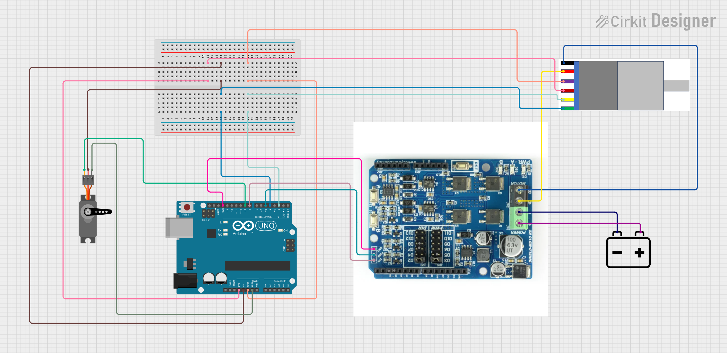
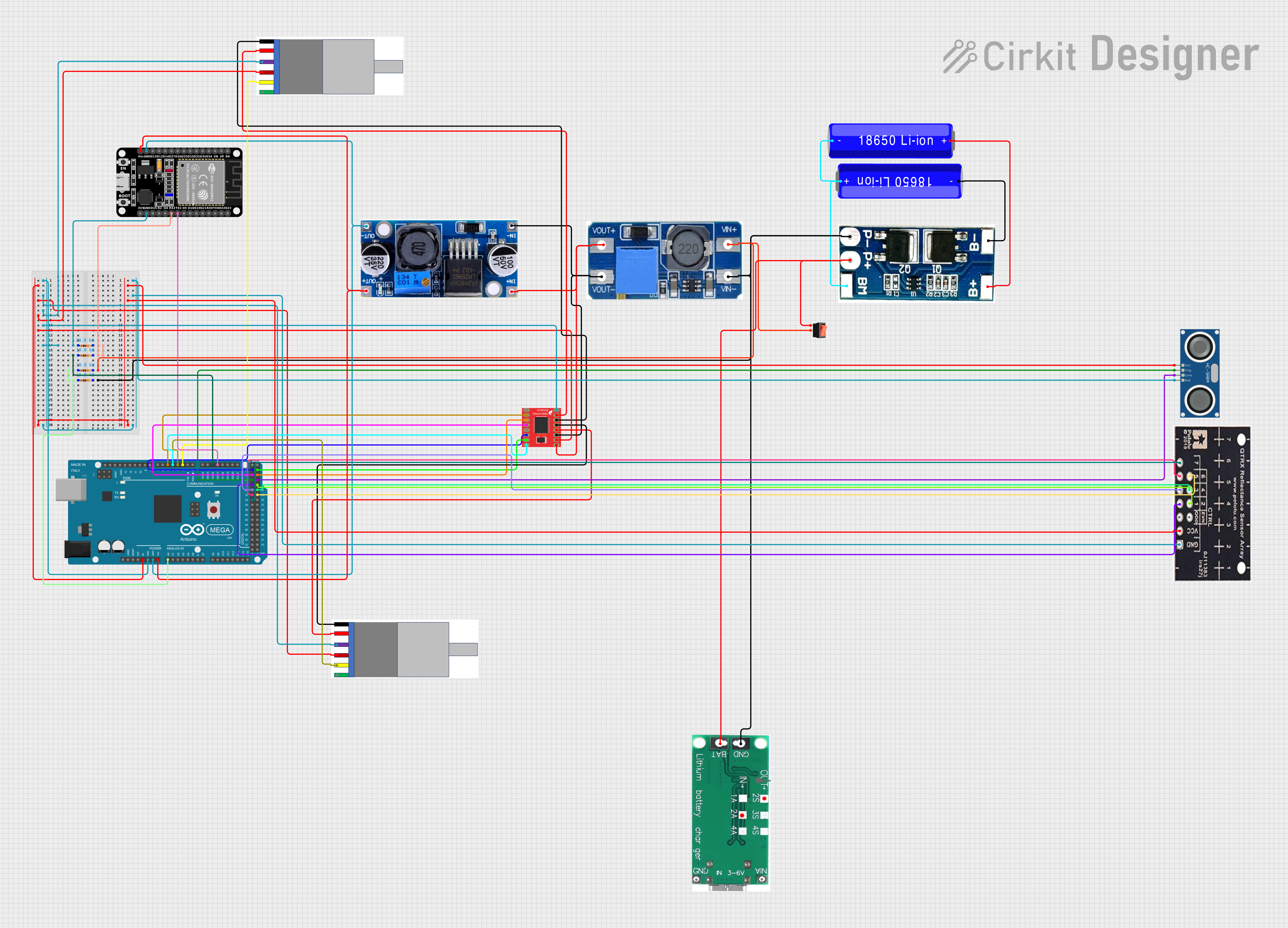
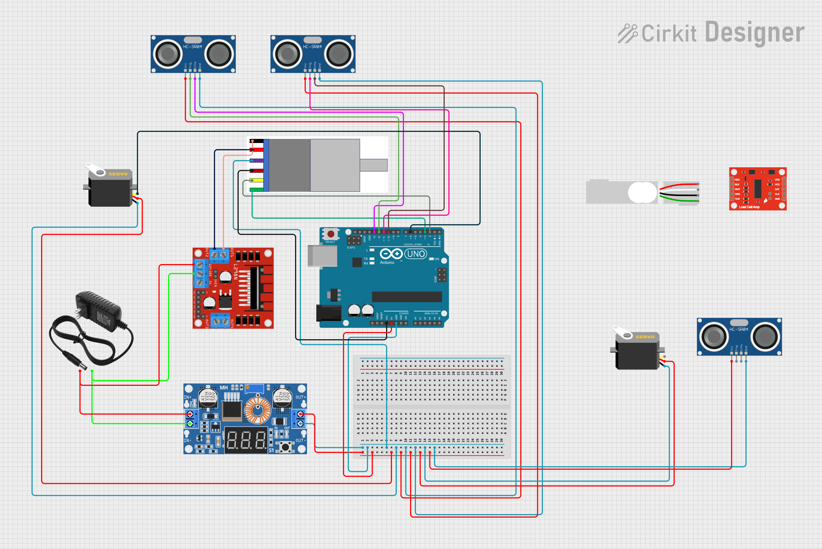
Connecting the Motor

  1. Connect the motor power pins to your power supply, ensuring that the voltage matches the rated voltage of the motor.
  2. Use a motor driver compatible with the motor's current requirements to control the motor's direction and speed.

Interfacing with the Encoder

  1. Connect the encoder Vcc and GND pins to a power source that matches the encoder's voltage requirements.
  2. Connect the encoder output channels (A and B) to the digital input pins on your microcontroller or interface board.

Best Practices

  • Always ensure that the power supply does not exceed the rated voltage of the motor.
  • Use a motor driver with overcurrent protection to prevent damage to the motor.
  • When connecting the encoder to a microcontroller, use pull-up resistors if required by the microcontroller's input circuitry.
  • Implement proper debouncing in software to ensure accurate reading of encoder signals.

Example Code for Arduino UNO

// Define motor control and encoder pins
const int motorPin1 = 3; // Motor control pin 1
const int motorPin2 = 4; // Motor control pin 2
const int encoderPinA = 2; // Encoder channel A
const int encoderPinB = 3; // Encoder channel B

// Variables to hold encoder count
volatile long encoderCount = 0;

// Interrupt service routine for encoder channel A
void encoderA_ISR() {
  // Determine direction based on channel B state
  if (digitalRead(encoderPinB) == HIGH) {
    encoderCount++;
  } else {
    encoderCount--;
  }
}

void setup() {
  // Set motor control pins as outputs
  pinMode(motorPin1, OUTPUT);
  pinMode(motorPin2, OUTPUT);

  // Set encoder pins as inputs
  pinMode(encoderPinA, INPUT);
  pinMode(encoderPinB, INPUT);

  // Attach interrupt for encoder channel A
  attachInterrupt(digitalPinToInterrupt(encoderPinA), encoderA_ISR, RISING);
}

void loop() {
  // Example: Drive motor forward
  digitalWrite(motorPin1, HIGH);
  digitalWrite(motorPin2, LOW);

  // Implement motor control logic and use encoderCount as needed
  // ...
}

Troubleshooting and FAQs

Common Issues

  • Motor does not turn: Check power supply connections and ensure the voltage is correct. Verify that the motor driver is functioning properly.
  • Encoder not providing output: Ensure that the encoder Vcc and GND are correctly connected and that the power supply voltage matches the encoder's requirements.
  • Inaccurate encoder readings: Confirm that the encoder pins are connected to the correct microcontroller pins. Check for proper debouncing in the software.

FAQs

Q: Can I use a different voltage supply for the motor? A: It is essential to use a power supply that matches the rated voltage of the motor to prevent damage.

Q: How can I reverse the motor direction? A: To reverse the motor direction, reverse the polarity of the motor power connections, either manually or using a motor driver.

Q: What is the purpose of the encoder? A: The encoder provides feedback on the motor shaft's position, speed, or direction, which is essential for precise control in closed-loop systems.

Q: How do I interpret the encoder signals? A: The encoder outputs two square wave signals (A and B) that are 90 degrees out of phase. By counting these pulses and observing the phase relationship, you can determine the position and direction of the motor shaft.

Remember to always follow safety guidelines when working with electronic components and consult the manufacturer's datasheet for specific details about the gear motor with integrated encoder by Naroote.