How to Use MPPT Solar Charge Controller: Examples, Pinouts, and Specs
Introduction
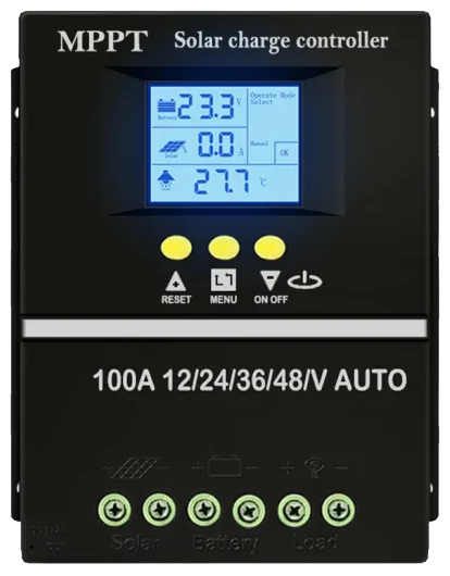
The MPPT Solar Charge Controller by PowMr is a high-efficiency device designed to optimize the power output from solar panels. By employing Maximum Power Point Tracking (MPPT) technology, it dynamically adjusts the electrical operating point of the solar modules to ensure maximum energy harvest. This controller is ideal for charging batteries in solar power systems, offering improved performance and energy conversion efficiency compared to traditional charge controllers.
Explore Projects Built with MPPT Solar Charge Controller
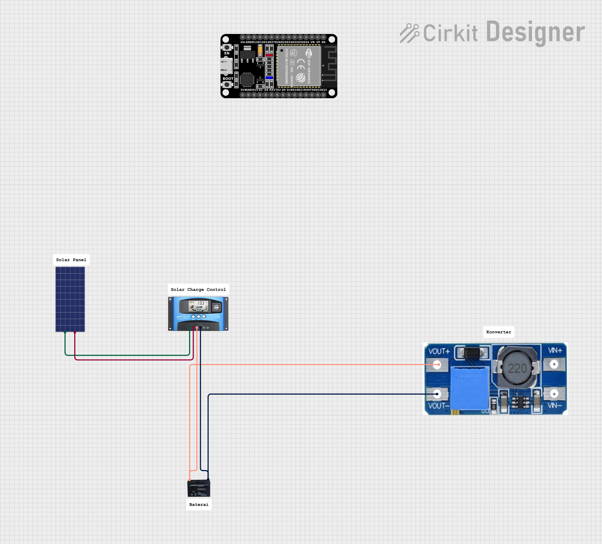
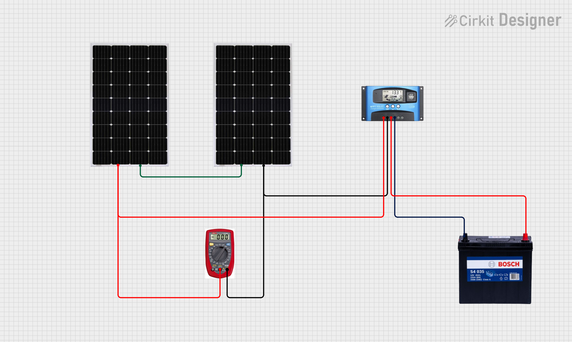
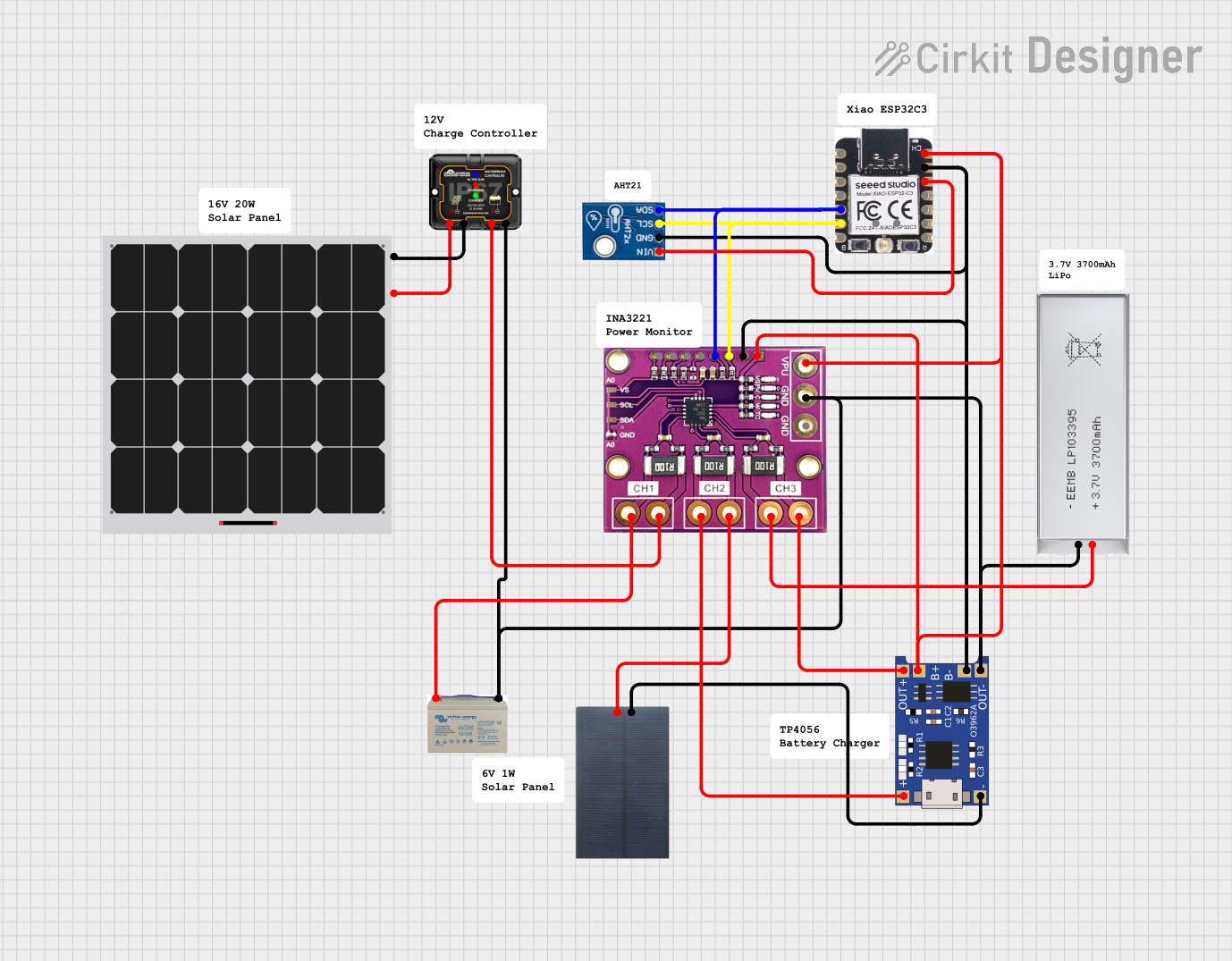
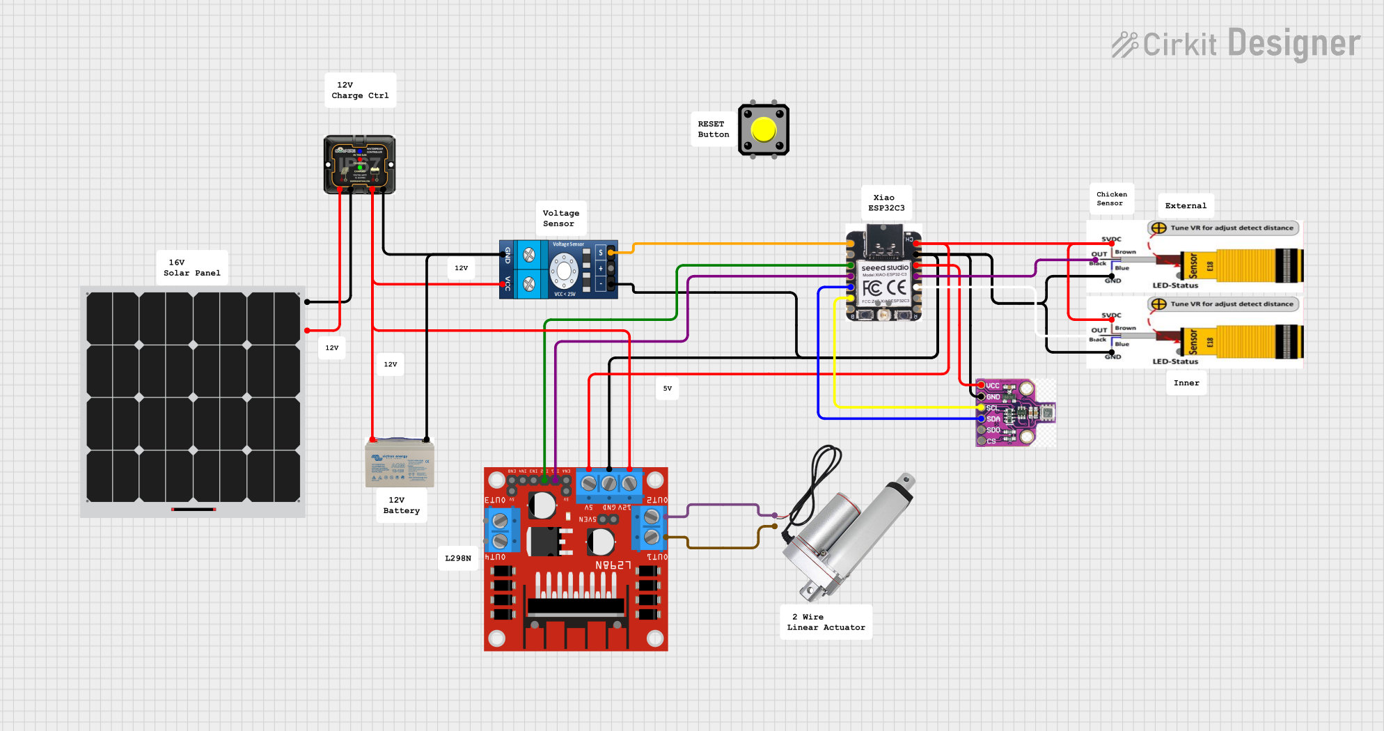
Explore Projects Built with MPPT Solar Charge Controller
Common Applications and Use Cases
- Off-grid solar power systems
- Residential and commercial solar installations
- Solar-powered RVs, boats, and caravans
- Backup power systems with battery storage
- Solar street lighting and remote monitoring systems
Technical Specifications
Key Technical Details
| Parameter | Specification |
|---|---|
| Input Voltage Range | 12V/24V/48V (auto-recognition) |
| Maximum Input Voltage | Up to 150V (depending on model) |
| Maximum Charging Current | 20A, 30A, 40A, 60A (model-dependent) |
| Efficiency | Up to 98% |
| Battery Types Supported | Lead-acid, AGM, Gel, Lithium-ion |
| Operating Temperature Range | -20°C to 60°C |
| Communication Interface | RS485, Bluetooth (optional) |
| Protection Features | Overcharge, over-discharge, short circuit, reverse polarity |
Pin Configuration and Descriptions
The MPPT Solar Charge Controller typically has the following terminal connections:
| Pin/Terminal Label | Description |
|---|---|
| PV+ | Positive terminal for solar panel input |
| PV- | Negative terminal for solar panel input |
| BAT+ | Positive terminal for battery connection |
| BAT- | Negative terminal for battery connection |
| LOAD+ | Positive terminal for DC load connection |
| LOAD- | Negative terminal for DC load connection |
| RS485/AUX | Communication interface for monitoring/control |
Usage Instructions
How to Use the Component in a Circuit
Connect the Solar Panels:
- Ensure the solar panel voltage is within the controller's input range.
- Connect the positive (+) and negative (-) terminals of the solar panel to the
PV+andPV-inputs on the controller.
Connect the Battery:
- Match the battery voltage to the controller's supported range (e.g., 12V, 24V, or 48V).
- Connect the positive (+) and negative (-) terminals of the battery to the
BAT+andBAT-terminals.
Connect the Load (Optional):
- If powering DC loads directly, connect the load's positive (+) and negative (-) terminals to the
LOAD+andLOAD-outputs.
- If powering DC loads directly, connect the load's positive (+) and negative (-) terminals to the
Power On:
- Once all connections are secure, the controller will automatically detect the system voltage and begin operation.
Monitor and Adjust Settings:
- Use the built-in display or communication interface (e.g., RS485 or Bluetooth) to monitor performance and adjust settings such as battery type, charging parameters, and load control.
Important Considerations and Best Practices
- Safety First: Always disconnect the battery and solar panel before making any wiring changes.
- Voltage Compatibility: Ensure the solar panel's open-circuit voltage (Voc) does not exceed the controller's maximum input voltage.
- Battery Type Selection: Configure the controller for the correct battery type to prevent overcharging or damage.
- Heat Dissipation: Install the controller in a well-ventilated area to prevent overheating.
- Fuse Protection: Use appropriate fuses or circuit breakers on the PV and battery lines for added safety.
Arduino UNO Integration Example
While the MPPT Solar Charge Controller is not directly controlled by an Arduino, it can be monitored using the RS485 interface. Below is an example of how to read data from the controller using an Arduino UNO:
#include <ModbusMaster.h>

// Create an instance of the ModbusMaster library
ModbusMaster node;

// Define the RS485 communication pins
#define RE_PIN 2  // Receiver Enable pin
#define DE_PIN 3  // Driver Enable pin

void preTransmission() {
  digitalWrite(RE_PIN, HIGH); // Enable transmission
  digitalWrite(DE_PIN, HIGH);
}

void postTransmission() {
  digitalWrite(RE_PIN, LOW);  // Disable transmission
  digitalWrite(DE_PIN, LOW);
}

void setup() {
  // Initialize serial communication
  Serial.begin(9600);
  Serial.println("MPPT Solar Charge Controller Monitoring");

  // Initialize RS485 communication pins
  pinMode(RE_PIN, OUTPUT);
  pinMode(DE_PIN, OUTPUT);
  postTransmission();

  // Initialize Modbus communication
  node.begin(1, Serial); // Set Modbus ID to 1
  node.preTransmission(preTransmission);
  node.postTransmission(postTransmission);
}

void loop() {
  uint8_t result;
  uint16_t data;

  // Read battery voltage (example register address: 0x3100)
  result = node.readInputRegisters(0x3100, 1);
  if (result == node.ku8MBSuccess) {
    data = node.getResponseBuffer(0);
    float batteryVoltage = data / 100.0; // Convert to volts
    Serial.print("Battery Voltage: ");
    Serial.print(batteryVoltage);
    Serial.println(" V");
  } else {
    Serial.println("Failed to read data from MPPT controller");
  }

  delay(1000); // Wait 1 second before the next read
}
Notes:
- Use an RS485-to-TTL module to connect the Arduino UNO to the MPPT controller.
- Refer to the MPPT controller's communication protocol for register addresses and data formats.
Troubleshooting and FAQs
Common Issues and Solutions
| Issue | Possible Cause | Solution |
|---|---|---|
| Controller not powering on | Incorrect wiring or no power input | Check all connections and ensure proper polarity. |
| Battery not charging | Solar panel voltage too low or battery issue | Verify solar panel output and battery health. |
| Overheating | Poor ventilation or excessive load | Install in a cooler, well-ventilated area. |
| Communication failure (RS485) | Incorrect wiring or baud rate mismatch | Verify RS485 connections and communication settings. |
FAQs
Can I use this controller with a lithium-ion battery?
- Yes, the controller supports lithium-ion batteries. Ensure the correct battery type is selected in the settings.
What happens if the solar panel voltage exceeds the maximum input?
- The controller may shut down or become damaged. Always ensure the panel's open-circuit voltage (Voc) is within the specified range.
Can I connect multiple solar panels?
- Yes, you can connect panels in series or parallel, but ensure the combined voltage and current are within the controller's limits.
How do I monitor the controller remotely?
- Use the RS485 interface or optional Bluetooth module to connect to a monitoring system or app.
By following this documentation, users can effectively integrate and operate the PowMr MPPT Solar Charge Controller in their solar power systems.