How to Use ATtiny1627: Examples, Pinouts, and Specs
Introduction
The ATtiny1627 is a low-power 8-bit microcontroller from Microchip Technology, featuring 16KB of Flash memory, 2KB of SRAM, and 256 bytes of EEPROM. It is designed for simple and efficient control applications, offering a rich set of peripherals and a high level of integration in a small package. This microcontroller is ideal for applications such as home automation, sensor interfacing, and small-scale embedded systems.
Explore Projects Built with ATtiny1627
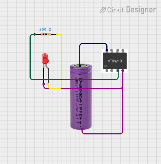

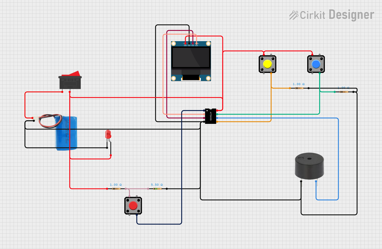

Explore Projects Built with ATtiny1627
Technical Specifications
Key Technical Details
| Parameter | Value |
|---|---|
| Flash Memory | 16KB |
| SRAM | 2KB |
| EEPROM | 256 bytes |
| Operating Voltage | 1.8V - 5.5V |
| CPU Speed | Up to 20 MHz |
| I/O Pins | 18 |
| ADC Channels | 12-bit, 10 channels |
| DAC Channels | 8-bit, 1 channel |
| Timers | 3 (16-bit) |
| Communication | USART, SPI, I2C |
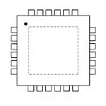
| Package | 20-pin SOIC, 24-pin QFN |
Pin Configuration and Descriptions
20-pin SOIC Package
| Pin No. | Pin Name | Description |
|---|---|---|
| 1 | VCC | Power Supply |
| 2 | GND | Ground |
| 3 | PA0 | I/O Pin, ADC0 |
| 4 | PA1 | I/O Pin, ADC1 |
| 5 | PA2 | I/O Pin, ADC2 |
| 6 | PA3 | I/O Pin, ADC3 |
| 7 | PA4 | I/O Pin, ADC4 |
| 8 | PA5 | I/O Pin, ADC5 |
| 9 | PA6 | I/O Pin, ADC6 |
| 10 | PA7 | I/O Pin, ADC7 |
| 11 | PB0 | I/O Pin, ADC8 |
| 12 | PB1 | I/O Pin, ADC9 |
| 13 | PB2 | I/O Pin, DAC0 |
| 14 | PB3 | I/O Pin |
| 15 | PB4 | I/O Pin |
| 16 | PB5 | I/O Pin |
| 17 | PB6 | I/O Pin |
| 18 | PB7 | I/O Pin |
| 19 | RESET | Reset Pin |
| 20 | XTAL | External Oscillator Pin |
Usage Instructions
How to Use the ATtiny1627 in a Circuit
- Power Supply: Connect the VCC pin to a stable power supply within the range of 1.8V to 5.5V. Connect the GND pin to the ground of the power supply.
- Reset: Connect a pull-up resistor (typically 10kΩ) between the RESET pin and VCC to ensure proper reset functionality.
- Oscillator: If using an external oscillator, connect it to the XTAL pin. Otherwise, the internal oscillator can be used.
- I/O Pins: Connect the I/O pins (PA0-PA7, PB0-PB7) to your peripherals or sensors as needed. Configure these pins in your code for input or output as required.
- Communication: Use the USART, SPI, or I2C pins for communication with other devices.
Important Considerations and Best Practices
- Decoupling Capacitors: Place decoupling capacitors (0.1µF) close to the VCC pin to filter out noise.
- Programming: Use an appropriate programmer (e.g., AVRISP mkII) to program the ATtiny1627. Ensure the correct fuse settings for your application.
- Power Consumption: Utilize sleep modes and power-saving features to minimize power consumption in battery-operated applications.
Example Code for Arduino UNO
// Example code to interface ATtiny1627 with Arduino UNO
// This code demonstrates basic digital I/O operations

void setup() {
  // Set pin modes
  pinMode(2, OUTPUT); // Set Arduino pin 2 as output
  pinMode(3, INPUT);  // Set Arduino pin 3 as input
}

void loop() {
  // Read the state of the input pin
  int sensorValue = digitalRead(3);

  // If the sensor is activated, turn on the LED
  if (sensorValue == HIGH) {
    digitalWrite(2, HIGH); // Turn on LED
  } else {
    digitalWrite(2, LOW);  // Turn off LED
  }

  delay(100); // Wait for 100 milliseconds
}
Troubleshooting and FAQs
Common Issues
Microcontroller Not Responding:
- Solution: Check the power supply connections and ensure the correct voltage is applied. Verify the reset pin configuration and ensure the pull-up resistor is connected.
Incorrect ADC Readings:
- Solution: Ensure the ADC reference voltage is stable and within the specified range. Check the input signal connections and ensure they are properly connected to the ADC pins.
Communication Failure:
- Solution: Verify the communication protocol settings (baud rate, data bits, etc.) and ensure they match between the ATtiny1627 and the connected device. Check the wiring connections for any loose or incorrect connections.
FAQs
Can I use the internal oscillator for my application?
- Yes, the ATtiny1627 has an internal oscillator that can be used for most applications. However, for precise timing requirements, an external oscillator may be preferred.
How do I program the ATtiny1627?
- You can use an AVR programmer such as the AVRISP mkII to program the ATtiny1627. Ensure you have the correct fuse settings and use the appropriate software (e.g., Atmel Studio) for programming.
What is the maximum operating frequency of the ATtiny1627?
- The ATtiny1627 can operate at a maximum frequency of 20 MHz.
By following this documentation, users can effectively utilize the ATtiny1627 microcontroller in their projects, ensuring proper setup, usage, and troubleshooting.