How to Use Receptor RC ga4htx: Examples, Pinouts, and Specs
Introduction
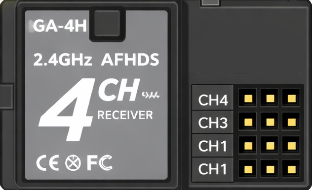
The Receptor RC GA4HTX is a specialized electronic component designed to receive and process signals. It is commonly used in communication systems, remote control devices, and sensor applications. Its ability to handle a wide range of frequencies and provide reliable signal processing makes it an essential component in modern electronics.
Explore Projects Built with Receptor RC ga4htx


Explore Projects Built with Receptor RC ga4htx
Common Applications:
- Wireless communication systems
- Remote control devices (e.g., drones, RC cars)
- Sensor data reception in IoT devices
- Signal processing in industrial automation systems
Technical Specifications
The following table outlines the key technical details of the Receptor RC GA4HTX:
| Parameter | Value |
|---|---|
| Operating Voltage | 3.3V to 5V |
| Operating Current | 10 mA (typical) |
| Frequency Range | 315 MHz to 433 MHz |
| Sensitivity | -105 dBm |
| Modulation Type | ASK (Amplitude Shift Keying) |
| Operating Temperature | -20°C to +70°C |
| Dimensions | 30mm x 14mm x 5mm |
Pin Configuration and Descriptions
The Receptor RC GA4HTX has a 4-pin configuration. The table below describes each pin:
| Pin Number | Pin Name | Description |
|---|---|---|
| 1 | VCC | Power supply input (3.3V to 5V) |
| 2 | GND | Ground connection |
| 3 | DATA | Signal output pin for processed data |
| 4 | ANT | Antenna connection for receiving signals |
Usage Instructions
How to Use the Receptor RC GA4HTX in a Circuit
- Power Supply: Connect the VCC pin to a 3.3V or 5V power source and the GND pin to the ground of your circuit.
- Signal Output: Connect the DATA pin to the input of a microcontroller or signal processing circuit.
- Antenna: Attach an appropriate antenna to the ANT pin to ensure optimal signal reception. The antenna length should match the operating frequency (e.g., ~17 cm for 433 MHz).
- Decoding Signals: Use a microcontroller or dedicated decoder IC to interpret the received signals from the DATA pin.
Important Considerations and Best Practices
- Antenna Placement: Ensure the antenna is placed away from noise sources (e.g., power lines, motors) to avoid interference.
- Power Supply Stability: Use a decoupling capacitor (e.g., 0.1 µF) near the VCC pin to stabilize the power supply.
- Signal Decoding: For microcontroller-based applications, libraries such as
RC-Switch(for Arduino) can simplify signal decoding. - Operating Environment: Avoid using the component in environments with extreme temperatures or high humidity.
Example: Connecting to an Arduino UNO
Below is an example of how to connect the Receptor RC GA4HTX to an Arduino UNO and decode signals:
Circuit Connections:
- Connect the VCC pin of the RC GA4HTX to the 5V pin on the Arduino.
- Connect the GND pin of the RC GA4HTX to the GND pin on the Arduino.
- Connect the DATA pin of the RC GA4HTX to digital pin 2 on the Arduino.
- Attach an appropriate antenna to the ANT pin.
Arduino Code Example:
#include <RCSwitch.h> // Include the RC-Switch library

RCSwitch mySwitch = RCSwitch(); // Create an instance of RCSwitch

void setup() {
  Serial.begin(9600); // Initialize serial communication at 9600 baud
  mySwitch.enableReceive(0); // Enable receiver on interrupt 0 (pin 2 on Arduino UNO)
}

void loop() {
  if (mySwitch.available()) {
    // Check if a signal is received
    int value = mySwitch.getReceivedValue();
    if (value == 0) {
      Serial.println("Unknown signal received"); // Handle unknown signals
    } else {
      Serial.print("Signal received: ");
      Serial.println(value); // Print the received signal value
    }
    mySwitch.resetAvailable(); // Reset the receiver for the next signal
  }
}
Troubleshooting and FAQs
Common Issues and Solutions
No Signal Received:
- Cause: Poor antenna connection or placement.
- Solution: Ensure the antenna is securely connected and positioned away from interference sources.
Unstable Signal Output:
- Cause: Power supply noise or insufficient decoupling.
- Solution: Add a 0.1 µF capacitor near the VCC pin to stabilize the power supply.
Incorrect Signal Decoding:
- Cause: Incompatible decoding library or incorrect frequency.
- Solution: Verify the frequency of the transmitter and ensure the correct library (e.g.,
RC-Switch) is used.
Component Overheating:
- Cause: Operating outside the specified voltage range.
- Solution: Ensure the supply voltage is within the 3.3V to 5V range.
FAQs
Q1: Can the Receptor RC GA4HTX work with 2.4 GHz signals?
A1: No, the RC GA4HTX is designed for frequencies between 315 MHz and 433 MHz. It cannot process 2.4 GHz signals.
Q2: What type of antenna should I use?
A2: A simple wire antenna with a length of approximately 17 cm is suitable for 433 MHz. For other frequencies, adjust the length accordingly.
Q3: Can I use this component with a Raspberry Pi?
A3: Yes, the DATA pin can be connected to a GPIO pin on the Raspberry Pi. However, you may need additional libraries or software for signal decoding.
Q4: Is the component compatible with digital and analog signals?
A4: The RC GA4HTX processes digital signals only. It is not designed for analog signal reception.