
How to Use Hirose DF13A-5P-1.25H Right-Angle Header: Examples, Pinouts, and Specs

 Design with Hirose DF13A-5P-1.25H Right-Angle Header in Cirkit Designer
Introduction
The Hirose DF13A-5P-1.25H is a 5-pin right-angle header connector designed for compact PCB applications. With a 1.25mm pitch, this connector is ideal for creating reliable and space-efficient connections in electronic circuits. Manufactured by Hirose Electric, this component is widely used in applications requiring robust and compact interconnections, such as consumer electronics, industrial equipment, and communication devices.
Explore Projects Built with Hirose DF13A-5P-1.25H Right-Angle Header
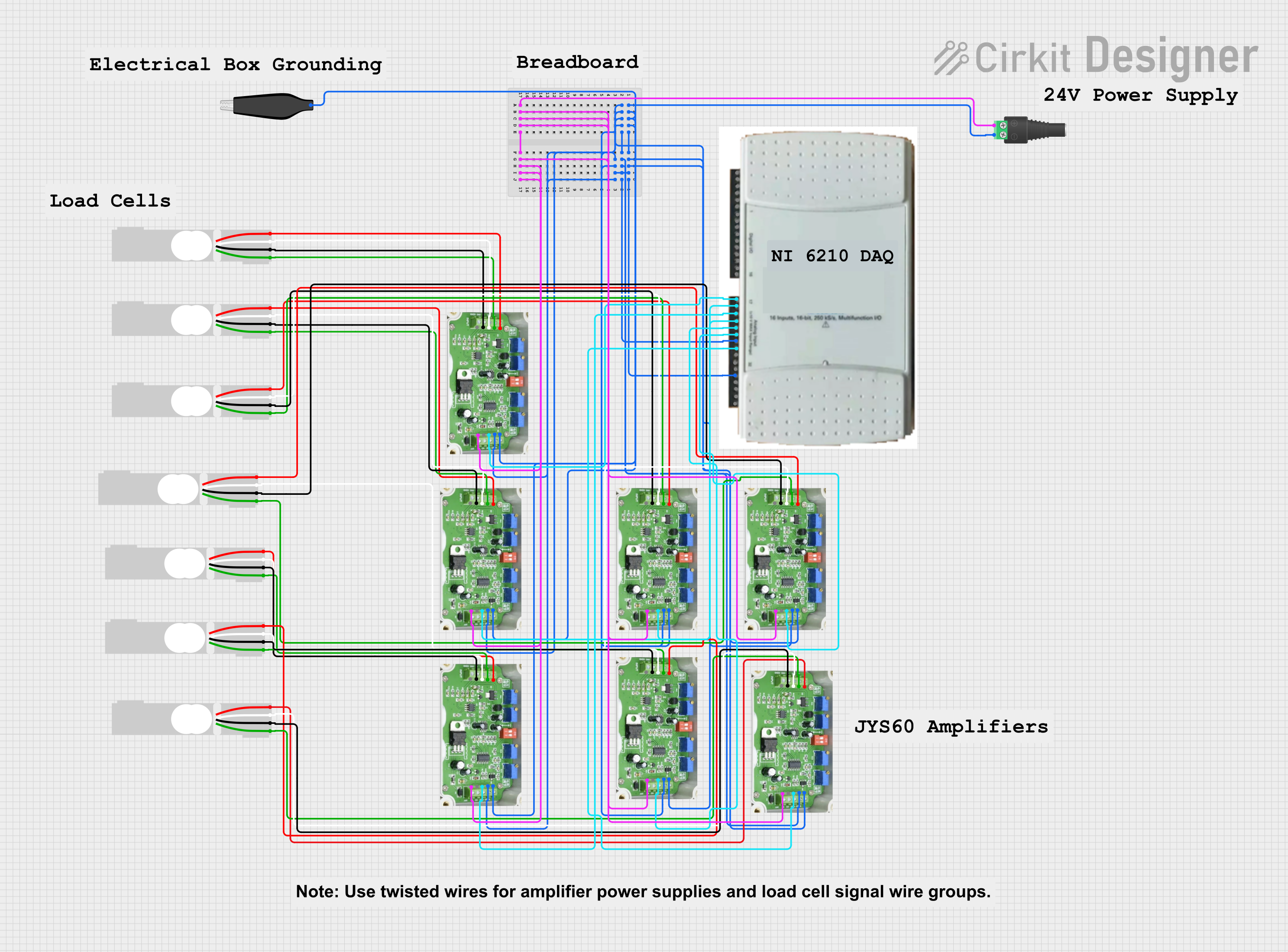 Open Project in Cirkit Designer
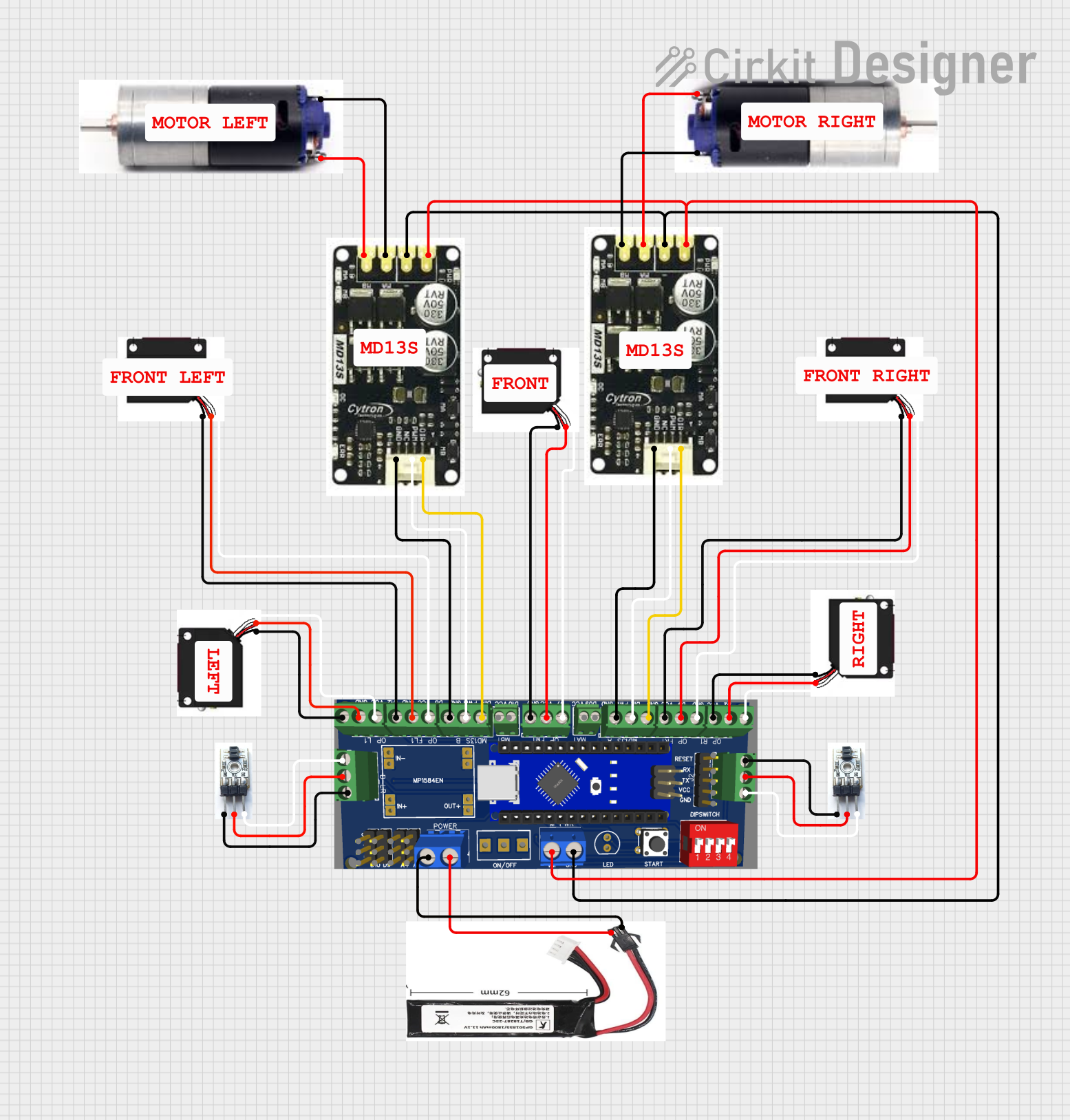 Open Project in Cirkit Designer
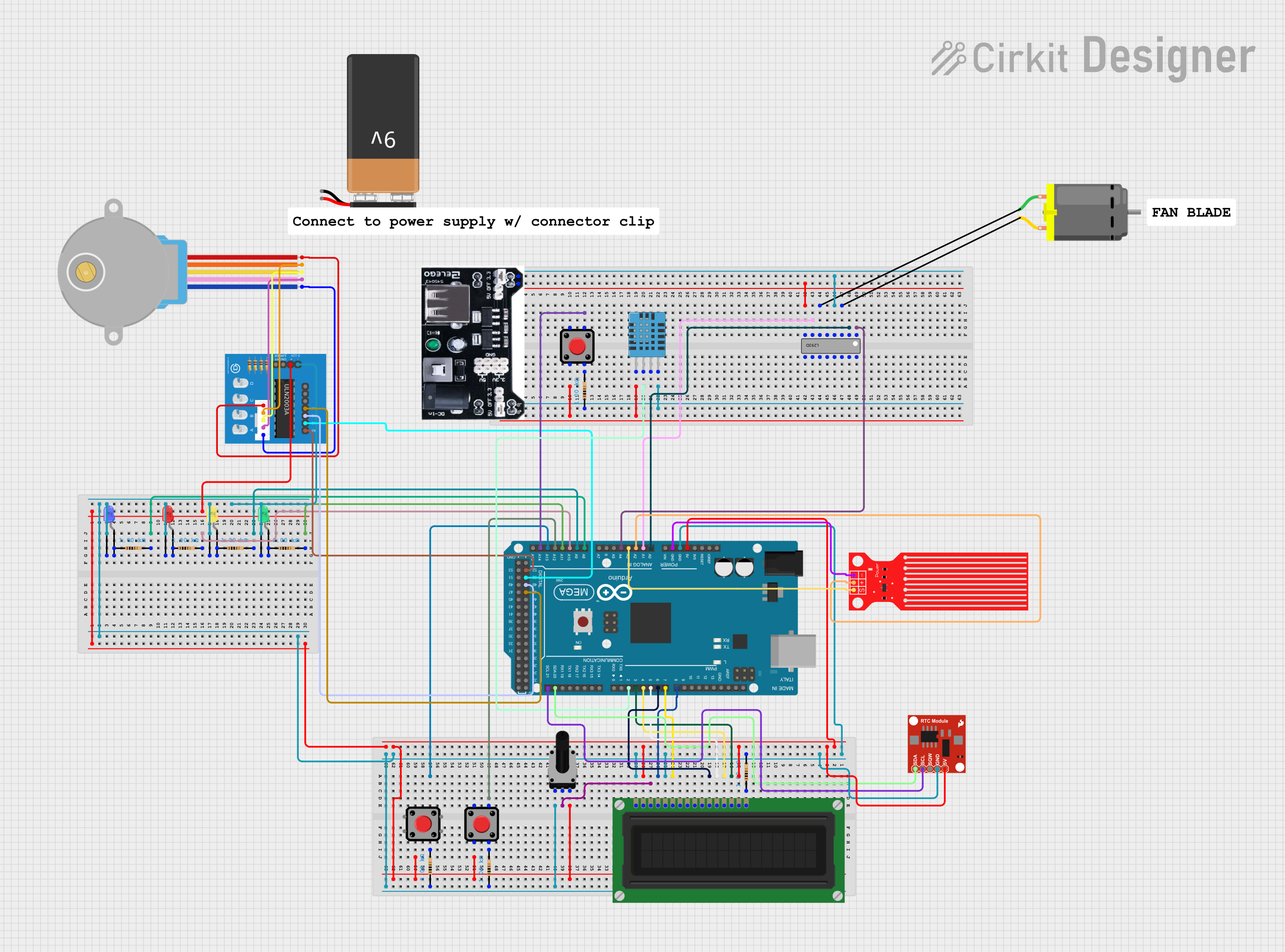 Open Project in Cirkit Designer
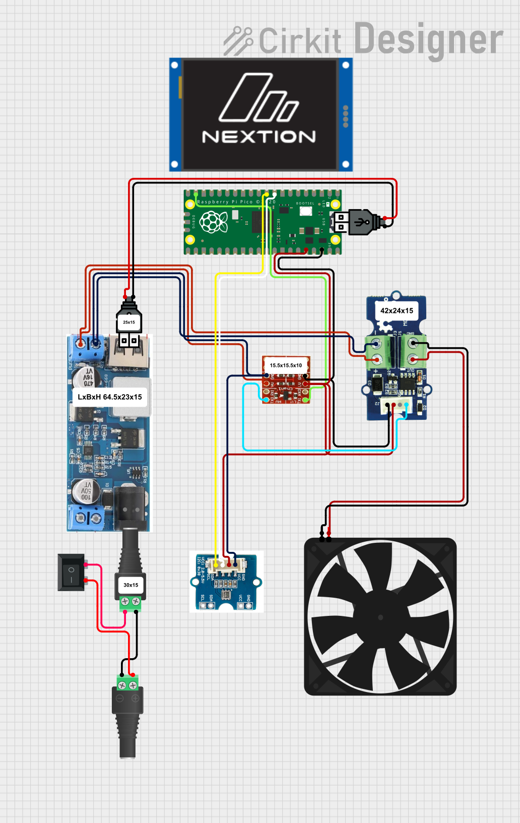 Open Project in Cirkit Designer
Explore Projects Built with Hirose DF13A-5P-1.25H Right-Angle Header
Open Project in Cirkit DesignerOpen Project in Cirkit DesignerOpen Project in Cirkit DesignerOpen Project in Cirkit DesignerCommon Applications
- Compact PCB designs in consumer electronics
- Signal and power connections in industrial equipment
- Communication devices and IoT modules
- Robotics and embedded systems
- Prototyping and development boards
Technical Specifications
Key Technical Details
| Parameter | Value |
|---|---|
| Manufacturer | Hirose Electric |
| Part Number | DF13A-5P-1.25H |
| Number of Pins | 5 |
| Pitch | 1.25mm |
| Mounting Type | Right-angle, through-hole |
| Current Rating | 1A per pin |
| Voltage Rating | 100V AC/DC |
| Operating Temperature | -35°C to +85°C |
| Contact Resistance | 30 mΩ max |
| Insulation Resistance | 1000 MΩ min at 100V DC |
| Material (Housing) | Polyamide (UL94V-0, flame-retardant) |
| Material (Contacts) | Phosphor bronze with tin plating |
Pin Configuration and Descriptions
The DF13A-5P-1.25H has five pins arranged in a single row with a 1.25mm pitch. Below is the pin configuration:
| Pin Number | Description | Notes |
|---|---|---|
| 1 | Signal/Power Line 1 | General-purpose connection |
| 2 | Signal/Power Line 2 | General-purpose connection |
| 3 | Signal/Power Line 3 | General-purpose connection |
| 4 | Signal/Power Line 4 | General-purpose connection |
| 5 | Signal/Power Line 5 | General-purpose connection |
Note: The pin assignments are generic and depend on the specific application. Always refer to your circuit design for proper pin usage.
Usage Instructions
How to Use the DF13A-5P-1.25H in a Circuit
PCB Design:
- Ensure the PCB layout matches the 1.25mm pitch of the connector.
- Use through-hole pads for the right-angle mounting pins.
- Verify the pin assignments in your schematic to match the connector's pinout.
Soldering:
- Use a soldering iron with a fine tip to solder the pins to the PCB.
- Avoid excessive heat to prevent damage to the connector housing.
- Inspect solder joints for proper connection and avoid cold solder joints.
Mating Connector:
- Use a compatible Hirose DF13 series receptacle or cable assembly for mating.
- Ensure proper alignment to avoid bending or damaging the pins.
Testing:
- After assembly, test the connections using a multimeter to verify continuity.
- Check for any short circuits between adjacent pins.
Important Considerations and Best Practices
- Mechanical Stress: Avoid applying excessive force to the connector during mating or unmating to prevent damage.
- Environmental Conditions: Ensure the operating environment is within the specified temperature range (-35°C to +85°C).
- Current and Voltage Ratings: Do not exceed the rated current (1A per pin) or voltage (100V AC/DC) to maintain safe operation.
- Connector Alignment: Always align the mating connector properly to avoid misalignment or pin damage.
Example: Using with an Arduino UNO
The DF13A-5P-1.25H can be used to connect sensors or modules to an Arduino UNO. Below is an example of connecting a sensor with a DF13-compatible cable:
// Example: Reading data from a sensor connected via DF13A-5P-1.25H
// Pin 1: VCC (3.3V or 5V from Arduino)
// Pin 2: GND (Ground)
// Pin 3: Signal (e.g., analog input to A0)

const int sensorPin = A0; // Define the analog pin connected to the sensor
int sensorValue = 0;      // Variable to store the sensor reading

void setup() {
  Serial.begin(9600); // Initialize serial communication
  pinMode(sensorPin, INPUT); // Set the sensor pin as input
}

void loop() {
  sensorValue = analogRead(sensorPin); // Read the sensor value
  Serial.print("Sensor Value: ");
  Serial.println(sensorValue); // Print the sensor value to the Serial Monitor
  delay(500); // Wait for 500ms before the next reading
}
Note: Ensure the sensor's power and signal levels are compatible with the Arduino UNO.
Troubleshooting and FAQs
Common Issues and Solutions
Loose Connections:
- Issue: The connector feels loose or does not make a proper connection.
- Solution: Verify that the mating connector is compatible and properly aligned. Check for bent or damaged pins.
Intermittent Signal:
- Issue: The signal is unstable or intermittent.
- Solution: Inspect solder joints for cold soldering or cracks. Ensure the connector is securely mounted.
Overheating:
- Issue: The connector or PCB area becomes hot during operation.
- Solution: Check that the current does not exceed the 1A per pin rating. Reduce the load if necessary.
Misalignment:
- Issue: The mating connector does not fit properly.
- Solution: Ensure proper alignment and avoid forcing the connection. Verify the connector type and orientation.
FAQs
Q1: Can the DF13A-5P-1.25H handle high-frequency signals?
A1: Yes, the connector can handle high-frequency signals, but ensure proper PCB design to minimize signal loss or interference.
Q2: Is the DF13A-5P-1.25H suitable for outdoor use?
A2: The connector is not specifically designed for outdoor use. If used outdoors, ensure proper environmental protection, such as enclosures or conformal coatings.
Q3: What is the recommended mating cycle for this connector?
A3: The DF13A-5P-1.25H is rated for approximately 30 mating cycles. Exceeding this may reduce reliability.
Q4: Can I use this connector for power delivery?
A4: Yes, but ensure the current does not exceed 1A per pin and the total power is within the voltage and current ratings.
By following this documentation, you can effectively integrate the Hirose DF13A-5P-1.25H into your electronic projects while ensuring reliable and safe operation.