How to Use Push Button: Examples, Pinouts, and Specs

Introduction
A push button is a momentary switch that completes an electrical circuit when pressed and breaks the circuit when released. It is widely used in electronic devices for user input, such as turning devices on/off, resetting systems, or triggering specific actions. Push buttons are simple, reliable, and versatile components that are essential in many electronic projects.
Explore Projects Built with Push Button


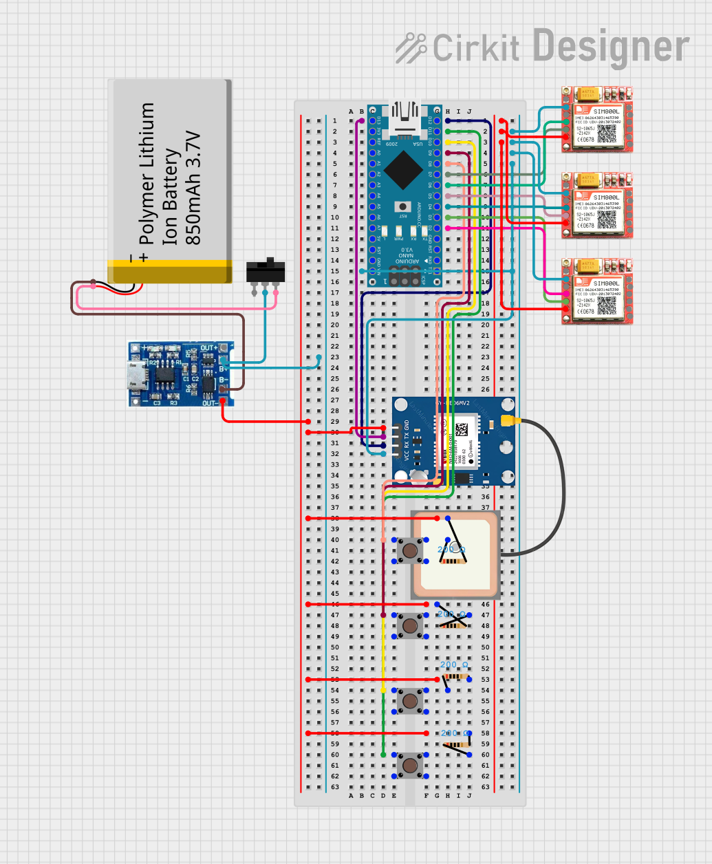
Explore Projects Built with Push Button
Common Applications and Use Cases
- Power buttons for electronic devices
- Reset switches in microcontroller circuits
- User input for embedded systems
- Triggering events in Arduino or Raspberry Pi projects
- Control panels and keypads
Technical Specifications
Below are the general technical specifications for a standard push button:
| Parameter | Value |
|---|---|
| Operating Voltage | 3.3V to 12V (typical) |
| Maximum Current Rating | 50mA to 500mA (depending on type) |
| Contact Resistance | ≤ 50 mΩ |
| Insulation Resistance | ≥ 100 MΩ |
| Operating Temperature | -20°C to +70°C |
| Mechanical Lifespan | 100,000 to 1,000,000 presses |
Pin Configuration and Descriptions
A standard push button typically has four pins, arranged in two pairs. The pins are internally connected as shown below:
| Pin Number | Description |
|---|---|
| Pin 1 | Connected to one side of the switch |
| Pin 2 | Internally connected to Pin 1 |
| Pin 3 | Connected to the other side of the switch |
| Pin 4 | Internally connected to Pin 3 |
Note: Pins 1 and 2 are electrically connected, as are Pins 3 and 4. This allows for flexible wiring in circuits.
Usage Instructions
How to Use the Push Button in a Circuit
- Identify the Pins: Use a multimeter to confirm which pins are internally connected (Pins 1 & 2, and Pins 3 & 4).
- Connect to the Circuit:
- Connect one pair of pins (e.g., Pins 1 and 2) to the input voltage or signal source.
- Connect the other pair (e.g., Pins 3 and 4) to the load or microcontroller input.
- Debounce the Button: Push buttons can produce noise or "bouncing" when pressed. Use a capacitor (e.g., 0.1µF) or software debounce techniques to ensure stable operation.
- Test the Circuit: Verify that the button completes the circuit when pressed and breaks it when released.
Important Considerations and Best Practices
- Debouncing: Always account for switch bounce in your design. This can be done using hardware (capacitors, resistors) or software (timing delays).
- Current Limiting: Ensure the current through the button does not exceed its maximum rating to avoid damage.
- Pull-Up or Pull-Down Resistors: When interfacing with microcontrollers, use pull-up or pull-down resistors to ensure a defined logic level when the button is not pressed.
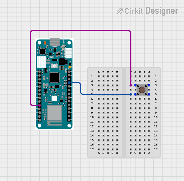
Example: Connecting a Push Button to an Arduino UNO
Below is an example of how to connect a push button to an Arduino UNO and read its state:
Circuit Diagram
- Connect one side of the push button to a digital input pin (e.g., Pin 2) on the Arduino.
- Connect the other side of the button to ground.
- Use the Arduino's internal pull-up resistor to ensure a stable HIGH state when the button is not pressed.
Code Example
// Push Button Example with Arduino UNO
// This code reads the state of a push button and turns on an LED when pressed.

const int buttonPin = 2;  // Pin connected to the push button
const int ledPin = 13;    // Pin connected to the onboard LED

void setup() {
  pinMode(buttonPin, INPUT_PULLUP); // Set button pin as input with internal pull-up
  pinMode(ledPin, OUTPUT);         // Set LED pin as output
}

void loop() {
  int buttonState = digitalRead(buttonPin); // Read the button state

  if (buttonState == LOW) { // Button is pressed (LOW due to pull-up resistor)
    digitalWrite(ledPin, HIGH); // Turn on the LED
  } else {
    digitalWrite(ledPin, LOW);  // Turn off the LED
  }
}
Note: The internal pull-up resistor ensures the button pin reads HIGH when the button is not pressed, avoiding floating pin issues.
Troubleshooting and FAQs
Common Issues and Solutions
Button Not Responding:
- Cause: Incorrect wiring or loose connections.
- Solution: Double-check the wiring and ensure all connections are secure.
Button Produces Erratic Behavior:
- Cause: Switch bounce.
- Solution: Add a debounce circuit (e.g., capacitor) or implement software debounce in your code.
Microcontroller Reads Incorrect State:
- Cause: Floating input pin.
- Solution: Use a pull-up or pull-down resistor to define the default state.
Button Feels Stuck or Unresponsive:
- Cause: Mechanical wear or debris.
- Solution: Clean the button or replace it if worn out.
FAQs
Q: Can I use a push button with high-current devices?
A: No, push buttons are designed for low-current applications. Use a relay or transistor to control high-current devices.
Q: How do I debounce a push button in software?
A: Introduce a small delay (e.g., 10-50ms) after detecting a button press to filter out noise caused by bouncing.
Q: Can I use a push button with analog signals?
A: Push buttons are typically used for digital signals (on/off). For analog signals, consider using a potentiometer or other analog input devices.