How to Use SPI OLED Display SSD1306 : Examples, Pinouts, and Specs
Introduction
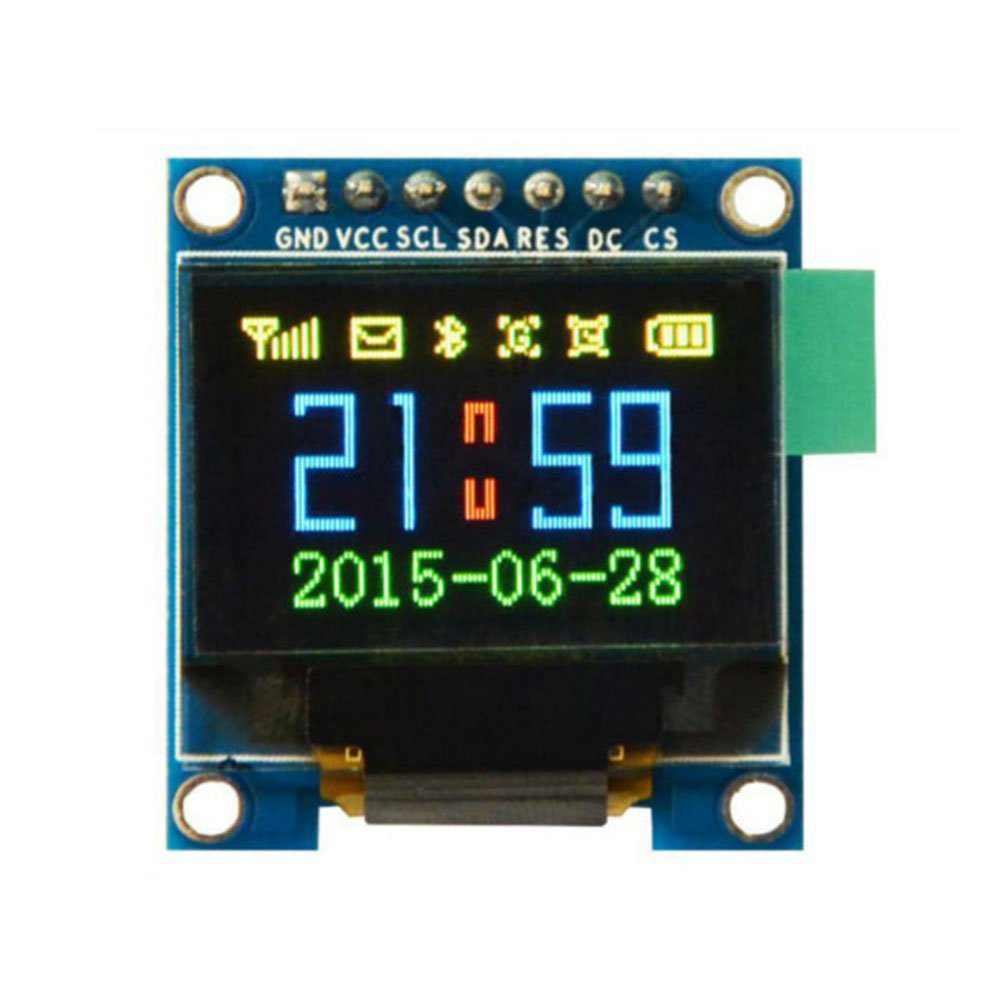
The SPI OLED Display SSD1306 is a compact, low-power OLED display module manufactured by STMicroelectronics (Part ID: SSD1331). It features a resolution of 128x64 pixels and utilizes the SSD1306 driver for efficient control and rendering of graphics and text. The display communicates via the SPI (Serial Peripheral Interface), enabling fast and reliable data transfer. Its small size, low power consumption, and high contrast make it ideal for a variety of embedded systems and IoT applications.
Explore Projects Built with SPI OLED Display SSD1306


Explore Projects Built with SPI OLED Display SSD1306
Common Applications and Use Cases
- Wearable devices and smartwatches
- IoT dashboards and status displays
- Portable medical devices
- Industrial control panels
- Hobbyist and DIY electronics projects
- Arduino and Raspberry Pi-based projects
Technical Specifications
Below are the key technical details and pin configuration for the SPI OLED Display SSD1306:
Key Technical Details
| Parameter | Value |
|---|---|
| Display Type | OLED (Organic Light Emitting Diode) |
| Resolution | 128x64 pixels |
| Driver IC | SSD1306 |
| Interface | SPI (4-wire) |
| Operating Voltage | 3.3V to 5V |
| Operating Current | ~20mA (typical) |
| Display Color | Monochrome (White) |
| Viewing Angle | >160° |
| Operating Temperature | -40°C to +85°C |
| Dimensions | ~27mm x 27mm x 4mm |
Pin Configuration and Descriptions
| Pin Name | Pin Number | Description |
|---|---|---|
| GND | 1 | Ground pin. Connect to the ground of the power supply. |
| VCC | 2 | Power supply pin. Connect to 3.3V or 5V. |
| D0 (SCK) | 3 | SPI Clock pin. Connect to the SPI clock line. |
| D1 (MOSI) | 4 | SPI Data pin. Connect to the SPI MOSI line. |
| RES | 5 | Reset pin. Used to reset the display module. |
| DC | 6 | Data/Command pin. High for data, low for commands. |
| CS | 7 | Chip Select pin. Active low to enable communication. |
Usage Instructions
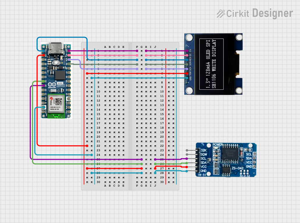
How to Use the Component in a Circuit
- Power Supply: Connect the VCC pin to a 3.3V or 5V power source and the GND pin to ground.
- SPI Connections:
- Connect the D0 (SCK) pin to the SPI clock pin of your microcontroller.
- Connect the D1 (MOSI) pin to the SPI MOSI pin of your microcontroller.
- Connect the CS pin to a GPIO pin configured as the SPI chip select.
- Control Pins:
- Connect the RES pin to a GPIO pin for resetting the display.
- Connect the DC pin to a GPIO pin to toggle between data and command modes.
- Initialization: Use the appropriate library (e.g., Adafruit SSD1306) to initialize and control the display.
Important Considerations and Best Practices
- Voltage Compatibility: Ensure the display's operating voltage matches your microcontroller's logic level (3.3V or 5V).
- SPI Speed: Use a moderate SPI clock speed (e.g., 1MHz to 4MHz) to ensure reliable communication.
- Reset Pin: Always reset the display during initialization to avoid unexpected behavior.
- Library Support: Use well-documented libraries like Adafruit SSD1306 or U8g2 for easier integration.
Example Code for Arduino UNO
Below is an example of how to use the SPI OLED Display SSD1306 with an Arduino UNO:
#include <Adafruit_GFX.h>      // Graphics library for OLED
#include <Adafruit_SSD1306.h> // SSD1306 driver library

#define SCREEN_WIDTH 128       // OLED display width, in pixels
#define SCREEN_HEIGHT 64       // OLED display height, in pixels

// Declaration for SPI SSD1306 display
#define OLED_MOSI   11         // SPI MOSI pin
#define OLED_CLK    13         // SPI Clock pin
#define OLED_DC     9          // Data/Command pin
#define OLED_CS     10         // Chip Select pin
#define OLED_RESET  8          // Reset pin

Adafruit_SSD1306 display(SCREEN_WIDTH, SCREEN_HEIGHT, &SPI, OLED_DC, OLED_RESET, OLED_CS);

void setup() {
  // Initialize the display
  if (!display.begin(SSD1306_SWITCHCAPVCC, 0x3C)) { // Address 0x3C for 128x64
    Serial.println(F("SSD1306 allocation failed"));
    for (;;); // Don't proceed, loop forever
  }

  display.clearDisplay(); // Clear the buffer
  display.setTextSize(1); // Set text size to 1
  display.setTextColor(SSD1306_WHITE); // Set text color to white
  display.setCursor(0, 0); // Set cursor to top-left corner
  display.println(F("Hello, SSD1306!")); // Print text
  display.display(); // Display the text
}

void loop() {
  // Add your code here for dynamic updates
}
Troubleshooting and FAQs
Common Issues and Solutions
Display Not Turning On:
- Verify the power connections (VCC and GND).
- Ensure the SPI connections are correct and secure.
- Check if the reset pin (RES) is properly connected and initialized.
No Output on the Display:
- Confirm the SPI clock speed is within the supported range.
- Ensure the correct I2C address (0x3C or 0x3D) is used in the code.
- Use a multimeter to check for continuity in the wiring.
Flickering or Corrupted Display:
- Reduce the SPI clock speed to improve stability.
- Ensure the power supply is stable and sufficient for the display.
Library Errors:
- Make sure the Adafruit SSD1306 library is installed and up to date.
- Verify that the correct pins are defined in the code.
FAQs
Q1: Can I use this display with a 3.3V microcontroller?
A1: Yes, the display is compatible with both 3.3V and 5V logic levels.
Q2: What is the maximum SPI clock speed supported?
A2: The SSD1306 driver typically supports SPI clock speeds up to 10MHz, but 1-4MHz is recommended for stability.
Q3: Can I use this display with I2C instead of SPI?
A3: No, this specific module is designed for SPI communication only. For I2C, use an SSD1306 module with I2C support.
Q4: How do I display custom graphics?
A4: Use the Adafruit GFX library to draw shapes, bitmaps, and other graphics on the display.
Q5: Is the display sunlight-readable?
A5: No, the display is not optimized for direct sunlight and is best used indoors or in shaded environments.