How to Use LSM6DSV32XTR: Examples, Pinouts, and Specs
Introduction
The LSM6DSV32XTR is a high-performance 6-axis inertial sensor manufactured by STMicroelectronics. It integrates a 3-axis accelerometer and a 3-axis gyroscope into a single compact package, enabling precise motion tracking and orientation detection. This sensor is designed for applications requiring low power consumption, high sensitivity, and real-time motion analysis.
Explore Projects Built with LSM6DSV32XTR


Explore Projects Built with LSM6DSV32XTR
Common Applications and Use Cases
- Smartphones and Tablets: For screen orientation, gesture recognition, and motion tracking.
- Wearable Devices: Fitness tracking, step counting, and activity monitoring.
- IoT Devices: Smart home automation, robotics, and industrial monitoring.
- Gaming and AR/VR: Motion sensing for immersive experiences.
- Drones and Robotics: Stabilization, navigation, and control systems.
Technical Specifications
Key Technical Details
| Parameter | Value |
|---|---|
| Operating Voltage | 1.71 V to 3.6 V |
| Accelerometer Full-Scale Range | ±2 g, ±4 g, ±8 g, ±16 g |
| Gyroscope Full-Scale Range | ±125 dps, ±250 dps, ±500 dps, ±1000 dps, ±2000 dps |
| Output Data Rate (ODR) | Up to 6.6 kHz for both accelerometer and gyroscope |
| Interface | I²C, SPI |
| Power Consumption | 0.55 mA in high-performance mode (accelerometer + gyroscope) |
| Operating Temperature Range | -40 °C to +85 °C |
| Package | LGA-14 (2.5 mm x 3 mm x 0.74 mm) |
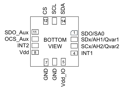
Pin Configuration and Descriptions
The LSM6DSV32XTR comes in a 14-pin LGA package. Below is the pin configuration:
| Pin Number | Pin Name | Description |
|---|---|---|
| 1 | VDD | Power supply (1.71 V to 3.6 V) |
| 2 | VDDIO | I/O interface voltage supply |
| 3 | GND | Ground |
| 4 | SCL/SPC | I²C clock line / SPI serial port clock |
| 5 | SDA/SDI/SDO | I²C data line / SPI serial data input/output |
| 6 | CS | SPI chip select (active low) |
| 7 | INT1 | Interrupt 1 output |
| 8 | INT2 | Interrupt 2 output |
| 9-14 | NC | Not connected (leave floating or connect to GND for stability) |
Usage Instructions
How to Use the LSM6DSV32XTR in a Circuit
- Power Supply: Connect the VDD pin to a 1.8 V or 3.3 V power source and the GND pin to ground. Ensure the VDDIO pin matches the logic level of your microcontroller (e.g., 3.3 V for most systems).
- Communication Interface: Choose between I²C or SPI:
- For I²C, connect the SCL and SDA pins to the corresponding I²C lines on your microcontroller. Use pull-up resistors (typically 4.7 kΩ) on both lines.
- For SPI, connect the SCL/SPC, SDA/SDI/SDO, and CS pins to the SPI lines on your microcontroller.
- Interrupts: Use the INT1 and INT2 pins to receive interrupt signals for specific events (e.g., motion detection).
- Bypass Unused Pins: Leave NC pins floating or connect them to GND for stability.
Important Considerations and Best Practices
- Decoupling Capacitors: Place a 0.1 µF ceramic capacitor close to the VDD and VDDIO pins to reduce noise.
- PCB Layout: Minimize trace lengths for the I²C or SPI lines to reduce signal degradation.
- Mounting Orientation: Ensure the sensor is mounted correctly to align with the desired axes of measurement.
- Configuration: Use the sensor's registers to configure the full-scale range, output data rate, and interrupt settings.
Example Code for Arduino UNO (I²C Interface)
Below is an example of how to initialize and read data from the LSM6DSV32XTR using an Arduino UNO:
#include <Wire.h>

// LSM6DSV32XTR I2C address
#define LSM6DSV32XTR_ADDR 0x6A

// Register addresses
#define WHO_AM_I 0x0F
#define CTRL1_XL 0x10
#define CTRL2_G  0x11
#define OUTX_L_XL 0x28

void setup() {
  Wire.begin(); // Initialize I2C communication
  Serial.begin(9600); // Initialize serial communication

  // Check if the sensor is connected
  Wire.beginTransmission(LSM6DSV32XTR_ADDR);
  Wire.write(WHO_AM_I);
  Wire.endTransmission();
  Wire.requestFrom(LSM6DSV32XTR_ADDR, 1);
  if (Wire.available()) {
    byte whoAmI = Wire.read();
    if (whoAmI == 0x6C) { // Expected WHO_AM_I response
      Serial.println("LSM6DSV32XTR detected!");
    } else {
      Serial.println("Device not recognized.");
      while (1);
    }
  }

  // Configure accelerometer (±2 g, 1.66 kHz ODR)
  Wire.beginTransmission(LSM6DSV32XTR_ADDR);
  Wire.write(CTRL1_XL);
  Wire.write(0x60); // 0x60 = 1.66 kHz ODR, ±2 g
  Wire.endTransmission();

  // Configure gyroscope (±250 dps, 1.66 kHz ODR)
  Wire.beginTransmission(LSM6DSV32XTR_ADDR);
  Wire.write(CTRL2_G);
  Wire.write(0x60); // 0x60 = 1.66 kHz ODR, ±250 dps
  Wire.endTransmission();
}

void loop() {
  // Read accelerometer X-axis data
  Wire.beginTransmission(LSM6DSV32XTR_ADDR);
  Wire.write(OUTX_L_XL);
  Wire.endTransmission();
  Wire.requestFrom(LSM6DSV32XTR_ADDR, 2);
  if (Wire.available() == 2) {
    int16_t accelX = Wire.read() | (Wire.read() << 8);
    Serial.print("Accel X: ");
    Serial.println(accelX);
  }

  delay(500); // Delay for readability
}
Troubleshooting and FAQs
Common Issues and Solutions
Sensor Not Detected:
- Ensure the I²C address (default: 0x6A) matches your configuration.
- Check the wiring and ensure pull-up resistors are present on the I²C lines.
- Verify the power supply voltage is within the specified range.
Incorrect or No Data Output:
- Confirm the sensor's registers are configured correctly (e.g., ODR, full-scale range).
- Check for noise or interference on the communication lines.
High Power Consumption:
- Use low-power modes if continuous high-performance operation is not required.
- Disable unused features via the sensor's registers.
FAQs
Q: Can the LSM6DSV32XTR operate in a low-power mode?
- A: Yes, the sensor supports multiple power modes to optimize energy consumption.
Q: What is the maximum output data rate?
- A: The maximum ODR is 6.6 kHz for both the accelerometer and gyroscope.
Q: Is the sensor compatible with 5 V logic?
- A: No, the sensor operates at 1.8 V or 3.3 V logic levels. Use a level shifter if needed.
Q: How do I reset the sensor?
- A: Write to the appropriate reset register (refer to the datasheet) or power cycle the device.