How to Use MD04: Examples, Pinouts, and Specs
Introduction
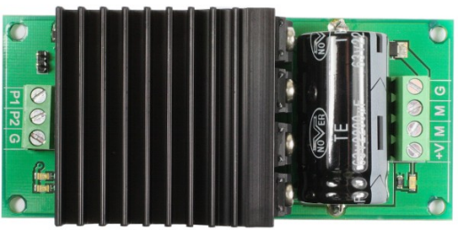
The MD04 is a motor driver module manufactured by ESP32 with the part ID 30pin. It is designed to control both DC motors and stepper motors, offering bidirectional control and the ability to manage multiple motors simultaneously. This makes the MD04 an excellent choice for robotics, automation, and other motor control applications. Its compact design and robust features make it suitable for hobbyists and professionals alike.
Explore Projects Built with MD04


Explore Projects Built with MD04
Common Applications
- Robotics projects requiring precise motor control
- Automation systems for industrial or home use
- Remote-controlled vehicles and drones
- Conveyor belt systems
- Educational projects involving motorized mechanisms
Technical Specifications
The MD04 motor driver module is built to handle a wide range of motor control tasks. Below are its key technical details:
General Specifications
| Parameter | Value |
|---|---|
| Manufacturer | ESP32 |
| Part ID | 30pin |
| Motor Types Supported | DC motors, Stepper motors |
| Control Type | Bidirectional |
| Number of Motors | Up to 2 motors simultaneously |
| Operating Voltage | 6V to 24V |
| Maximum Current | 5A per channel |
| PWM Frequency | Up to 20 kHz |
| Communication Interface | GPIO pins (PWM, DIR, EN) |
| Dimensions | 50mm x 40mm x 15mm |
Pin Configuration
The MD04 module features a 30-pin interface for motor control and power connections. Below is the pin configuration:
| Pin Number | Pin Name | Description |
|---|---|---|
| 1 | VM+ | Motor power supply positive terminal (6V to 24V) |
| 2 | GND | Ground connection for motor power supply |
| 3 | M1+ | Positive terminal for Motor 1 |
| 4 | M1- | Negative terminal for Motor 1 |
| 5 | M2+ | Positive terminal for Motor 2 |
| 6 | M2- | Negative terminal for Motor 2 |
| 7 | PWM1 | PWM input for Motor 1 speed control |
| 8 | DIR1 | Direction control input for Motor 1 |
| 9 | EN1 | Enable input for Motor 1 (active HIGH) |
| 10 | PWM2 | PWM input for Motor 2 speed control |
| 11 | DIR2 | Direction control input for Motor 2 |
| 12 | EN2 | Enable input for Motor 2 (active HIGH) |
| 13-30 | NC | Not connected (reserved for future use or custom configurations) |
Usage Instructions
How to Use the MD04 in a Circuit
- Power Supply: Connect the VM+ pin to a power source (6V to 24V) and the GND pin to ground.
- Motor Connections: Attach the motor terminals to the M1+/M1- and M2+/M2- pins.
- Control Signals: Use GPIO pins from a microcontroller (e.g., Arduino UNO or ESP32) to send PWM, DIR, and EN signals to the MD04.
- Enable Motors: Set the EN1 and EN2 pins HIGH to enable Motor 1 and Motor 2, respectively.
- Speed Control: Adjust the PWM signal duty cycle to control motor speed.
- Direction Control: Set the DIR1 and DIR2 pins HIGH or LOW to control the rotation direction of each motor.
Important Considerations
- Ensure the power supply voltage matches the motor's operating range.
- Use appropriate heat sinks or cooling mechanisms if operating near the maximum current limit (5A per channel).
- Avoid reversing the power supply polarity to prevent damage to the module.
- Use decoupling capacitors near the power supply pins to reduce noise and voltage spikes.
Example Code for Arduino UNO
Below is an example code snippet to control two DC motors using the MD04 module and an Arduino UNO:
// Define motor control pins
#define EN1 9    // Enable pin for Motor 1
#define DIR1 8   // Direction pin for Motor 1
#define PWM1 10  // PWM pin for Motor 1

#define EN2 7    // Enable pin for Motor 2
#define DIR2 6   // Direction pin for Motor 2
#define PWM2 5   // PWM pin for Motor 2

void setup() {
  // Set motor control pins as outputs
  pinMode(EN1, OUTPUT);
  pinMode(DIR1, OUTPUT);
  pinMode(PWM1, OUTPUT);

  pinMode(EN2, OUTPUT);
  pinMode(DIR2, OUTPUT);
  pinMode(PWM2, OUTPUT);

  // Enable both motors
  digitalWrite(EN1, HIGH);
  digitalWrite(EN2, HIGH);
}

void loop() {
  // Motor 1: Forward at 50% speed
  digitalWrite(DIR1, HIGH);  // Set direction to forward
  analogWrite(PWM1, 128);    // Set speed (128/255 = 50%)

  // Motor 2: Reverse at 75% speed
  digitalWrite(DIR2, LOW);   // Set direction to reverse
  analogWrite(PWM2, 192);    // Set speed (192/255 = 75%)

  delay(2000);  // Run motors for 2 seconds

  // Stop both motors
  analogWrite(PWM1, 0);
  analogWrite(PWM2, 0);

  delay(1000);  // Wait for 1 second before repeating
}
Troubleshooting and FAQs
Common Issues and Solutions
Motors Not Running
- Cause: EN pins are not set HIGH.
- Solution: Ensure the EN1 and EN2 pins are set HIGH to enable the motors.
Motor Speed Not Changing
- Cause: Incorrect PWM signal or duty cycle.
- Solution: Verify the PWM signal is being sent correctly and adjust the duty cycle as needed.
Overheating
- Cause: Exceeding the maximum current rating (5A per channel).
- Solution: Use motors within the current limit and add heat sinks or cooling fans.
No Response from Module
- Cause: Incorrect wiring or power supply issues.
- Solution: Double-check all connections and ensure the power supply voltage is within the specified range.
FAQs
Q: Can the MD04 control stepper motors?
A: Yes, the MD04 can control stepper motors, but you will need to implement the appropriate stepper motor control logic in your microcontroller code.
Q: Is the MD04 compatible with 3.3V logic?
A: Yes, the MD04 is compatible with both 3.3V and 5V logic levels, making it suitable for use with a wide range of microcontrollers.
Q: Can I use the MD04 to control more than two motors?
A: No, the MD04 is designed to control up to two motors simultaneously. For additional motors, you will need multiple MD04 modules.