How to Use ESP-01 Breadboard Adapter: Examples, Pinouts, and Specs
Introduction
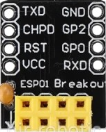
The ESP-01 Breadboard Adapter is a convenient breakout board designed to facilitate the use of the ESP-01 Wi-Fi module with standard breadboards. The ESP-01 module, powered by the ESP8266 microcontroller, is a popular choice for adding Wi-Fi functionality to various electronic projects. The adapter board addresses the ESP-01's non-breadboard-friendly pin layout by adapting it to a standard 0.1-inch (2.54mm) pitch, allowing for easy plug-and-play prototyping.
Explore Projects Built with ESP-01 Breadboard Adapter


Explore Projects Built with ESP-01 Breadboard Adapter
Common Applications and Use Cases
- Internet of Things (IoT) devices
- Home automation systems
- Wireless sensor networks
- DIY electronics projects
Technical Specifications
Key Technical Details
- Voltage: 3.3V (Do not exceed 3.6V)
- Current: Depends on ESP-01 usage, typically up to 300mA during transmission
- Dimensions: Matches standard breadboard with 0.1-inch pitch
Pin Configuration and Descriptions
| Pin Number | Description | Notes |
|---|---|---|
| 1 | GND | Ground |
| 2 | GPIO2 | General Purpose Input/Output 2 |
| 3 | GPIO0 | General Purpose Input/Output 0 |
| 4 | RX | Receive Data (Serial) |
| 5 | TX | Transmit Data (Serial) |
| 6 | CH_PD | Chip Power-Down (Active High) |
| 7 | RST | Reset Pin (Active Low) |
| 8 | VCC | 3.3V Power Supply |
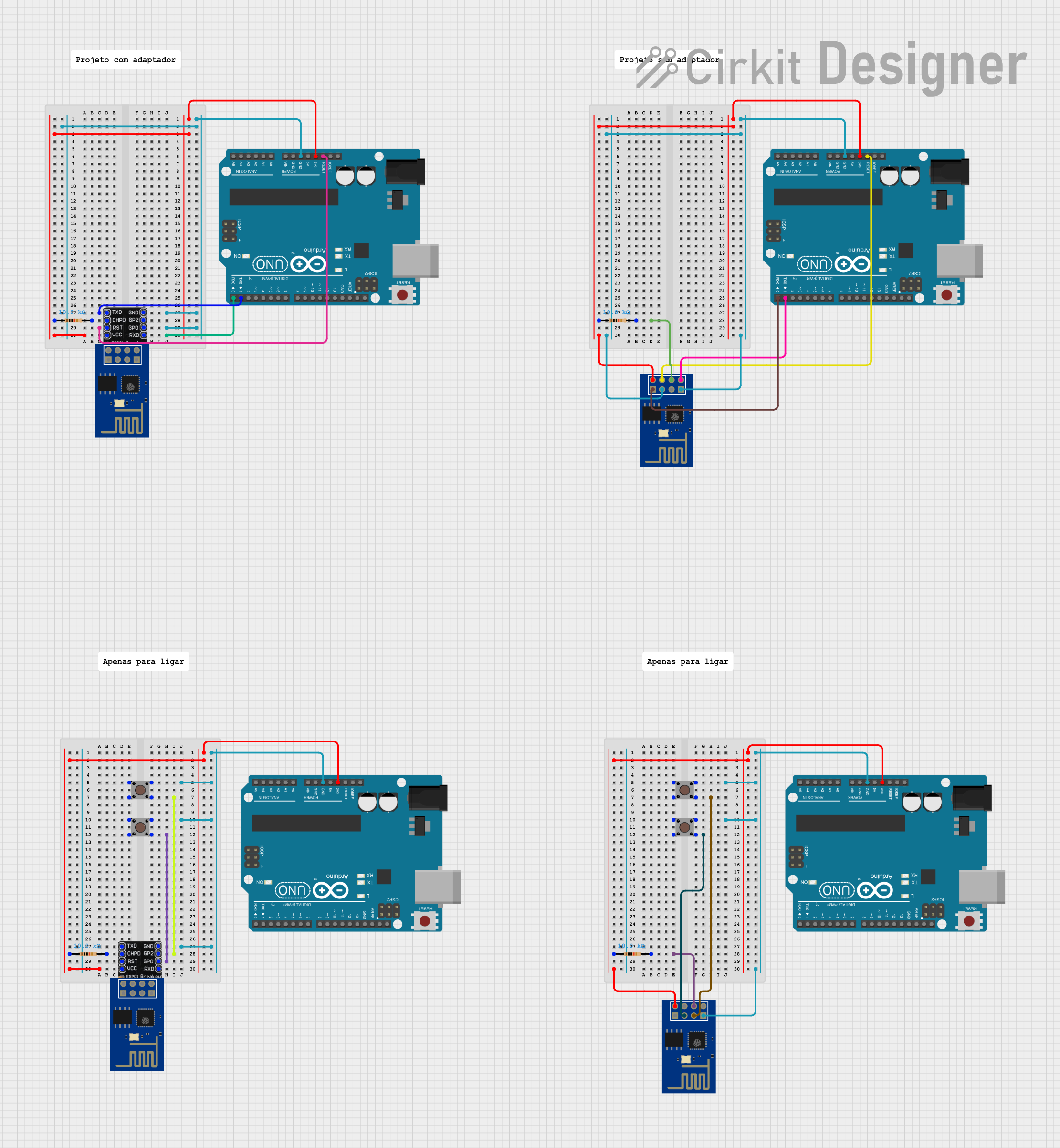
Usage Instructions
How to Use the Component in a Circuit
- Power Supply: Ensure that the power supply to the ESP-01 Breadboard Adapter is 3.3V. Exceeding this voltage can damage the ESP-01 module.
- Insertion: Carefully insert the ESP-01 module into the adapter, aligning the pins correctly.
- Breadboarding: Place the adapter onto the breadboard, ensuring that the pins are securely inserted into the breadboard sockets.
- Connections: Connect the adapter pins to the appropriate points in your circuit, such as GPIOs to sensors or actuators, TX/RX for serial communication, etc.
- Programming: The ESP-01 module can be programmed using the Arduino IDE or other development environments. Ensure GPIO0 is grounded during programming to enable the flash mode.
Important Considerations and Best Practices
- Antenna Clearance: Ensure that the ESP-01's antenna has enough clearance from metal objects to avoid signal interference.
- Decoupling Capacitors: Place a 0.1uF capacitor close to the VCC and GND pins to stabilize the power supply.
- Serial Communication: When using TX and RX for serial communication, remember that the ESP-01 operates at 3.3V logic levels. Use a logic level converter if interfacing with 5V devices.
Troubleshooting and FAQs
Common Issues Users Might Face
- Power Issues: If the ESP-01 fails to power up, check the power supply and connections. Ensure that the voltage is steady at 3.3V.
- Programming Issues: If programming fails, ensure that GPIO0 is grounded and the correct serial port and board settings are selected in the IDE.
- Connection Issues: If the module does not connect to a network, verify the Wi-Fi credentials and signal strength.
Solutions and Tips for Troubleshooting
- LED Indicators: Use the onboard LED indicators on the ESP-01 to diagnose power and activity status.
- Serial Monitor: Use the serial monitor in the Arduino IDE to debug and monitor the output from the ESP-01.
- Re-flashing Firmware: If the module is unresponsive, re-flashing the firmware may be necessary.
FAQs
Q: Can I power the ESP-01 with 5V?
- A: No, the ESP-01 requires a 3.3V power supply. Using 5V can permanently damage the module.
Q: How do I reset the ESP-01?
- A: Briefly connect the RST pin to GND to reset the module.
Q: Can I use the ESP-01 adapter with a 5V Arduino?
- A: Yes, but ensure that the voltage levels on the TX and RX pins are shifted to 3.3V to avoid damaging the ESP-01.
Example Arduino UNO Code
#include <ESP8266WiFi.h>

// Replace with your network credentials
const char* ssid = "your_SSID";
const char* password = "your_PASSWORD";

void setup() {
  Serial.begin(115200); // Start serial communication at 115200 baud
  WiFi.begin(ssid, password); // Connect to Wi-Fi

  while (WiFi.status() != WL_CONNECTED) {
    delay(500);
    Serial.print(".");
  }

  Serial.println("");
  Serial.println("WiFi connected.");
  Serial.print("IP address: ");
  Serial.println(WiFi.localIP()); // Print the local IP address
}

void loop() {
  // Your code here
}
Note: This code assumes that the ESP-01 is already programmed with the appropriate bootloader and is ready to accept Arduino sketches. Make sure to select the correct board (Generic ESP8266 Module) and port in the Arduino IDE before uploading the sketch.