How to Use Multiplexer: Examples, Pinouts, and Specs
Introduction
A multiplexer, often abbreviated as MUX, is a digital switch that selects one of several input signals and forwards the selected input to a single output line. It is a combinational logic circuit widely used in digital electronics for data routing, signal selection, and communication systems. By using control signals, a multiplexer can dynamically choose which input to forward, making it an essential component in applications requiring efficient data management.
Explore Projects Built with Multiplexer


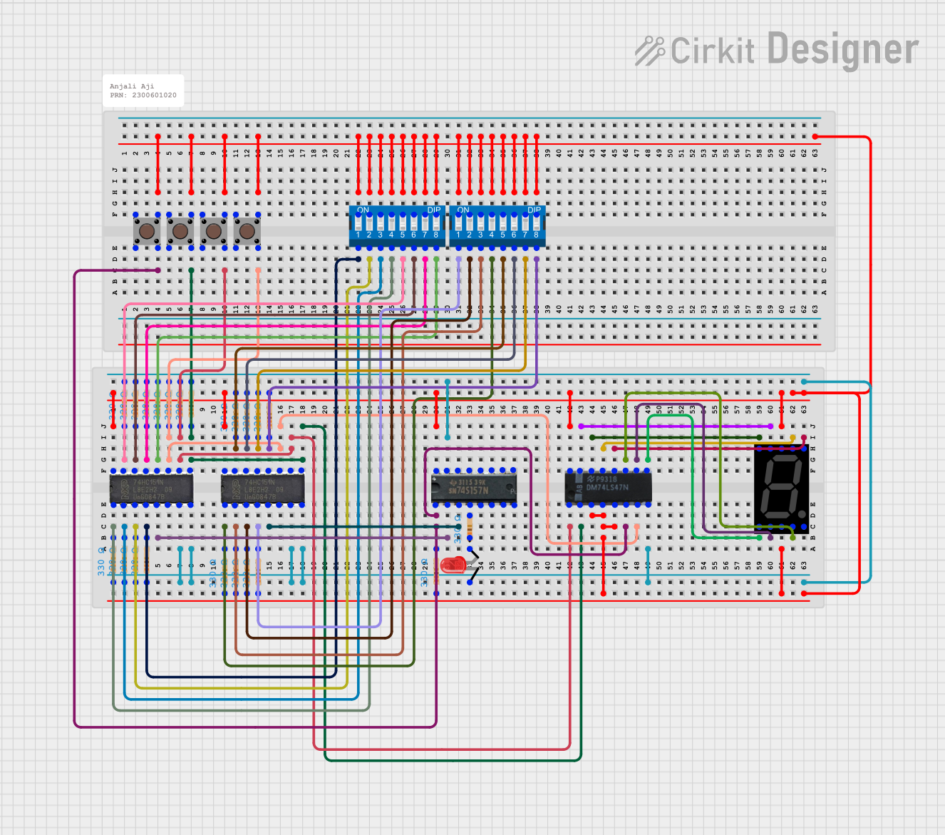

Explore Projects Built with Multiplexer
Common Applications and Use Cases
- Data routing in communication systems
- Signal selection in microcontrollers and processors
- Memory addressing in computer systems
- Analog-to-digital conversion systems
- Multiplexed display systems (e.g., 7-segment displays)
Technical Specifications
Below are the general technical specifications for a standard 4-to-1 multiplexer (e.g., 74HC157):
Key Technical Details
- Supply Voltage (Vcc): 2V to 6V (typical: 5V)
- Input Voltage Range: 0V to Vcc
- Output Voltage Range: 0V to Vcc
- Propagation Delay: ~10ns to 20ns (varies by model and supply voltage)
- Power Consumption: Low power CMOS technology
- Control Inputs: Binary select lines to choose the input
- Number of Inputs: 4 (for a 4-to-1 multiplexer)
- Output: 1 output line
- Enable Pin: Active HIGH or LOW (depending on the model)
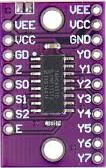
Pin Configuration and Descriptions
The following table describes the pinout for a typical 4-to-1 multiplexer (e.g., 74HC157):
| Pin Number | Pin Name | Description |
|---|---|---|
| 1 | A | Input A (Data Input 1) |
| 2 | B | Input B (Data Input 2) |
| 3 | C | Input C (Data Input 3) |
| 4 | D | Input D (Data Input 4) |
| 5 | S0 | Select Line 0 (Control Input) |
| 6 | S1 | Select Line 1 (Control Input) |
| 7 | GND | Ground (0V reference) |
| 8 | Y | Output (Selected Input) |
| 9 | Enable | Enable Pin (Active HIGH or LOW, model-specific) |
| 10 | Vcc | Power Supply (2V to 6V) |
Usage Instructions
How to Use the Component in a Circuit
Connect Power Supply:
- Connect the Vcc pin to a stable power source (e.g., 5V for most models).
- Connect the GND pin to the ground of the circuit.
Connect Input Signals:
- Attach the input signals to the data input pins (A, B, C, D for a 4-to-1 multiplexer).
Set Control Signals:
- Use the select lines (S0, S1) to choose which input signal to forward to the output.
- For example, if S0 = 0 and S1 = 1, the multiplexer will forward Input B to the output.
Enable the Multiplexer:
- Ensure the Enable pin is set to the appropriate logic level (HIGH or LOW) based on the model.
Read the Output:
- The selected input signal will appear on the output pin (Y).
Important Considerations and Best Practices
- Decoupling Capacitor: Place a 0.1µF decoupling capacitor near the Vcc pin to reduce noise and stabilize the power supply.
- Unused Inputs: Tie unused input pins to GND or Vcc to avoid floating inputs, which can cause erratic behavior.
- Control Signal Timing: Ensure the control signals (S0, S1) are stable before reading the output to avoid glitches.
- Voltage Levels: Verify that the input and control signal voltage levels match the multiplexer’s operating range.
Example: Connecting a Multiplexer to an Arduino UNO
Below is an example of how to use a 4-to-1 multiplexer with an Arduino UNO to select one of four analog signals:
Circuit Connections
- Connect the multiplexer’s Vcc to the Arduino’s 5V pin and GND to GND.
- Connect the multiplexer’s select lines (S0, S1) to Arduino digital pins 2 and 3.
- Connect the Enable pin to GND (active LOW model).
- Connect the data inputs (A, B, C, D) to four analog signal sources.
- Connect the output (Y) to an Arduino analog input pin (e.g., A0).
Arduino Code
// Define control pins for the multiplexer
const int selectPin0 = 2; // S0 connected to digital pin 2
const int selectPin1 = 3; // S1 connected to digital pin 3
const int outputPin = A0; // Y connected to analog pin A0

void setup() {
  // Set select pins as outputs
  pinMode(selectPin0, OUTPUT);
  pinMode(selectPin1, OUTPUT);

  // Initialize serial communication for debugging
  Serial.begin(9600);
}

void loop() {
  for (int i = 0; i < 4; i++) {
    // Set the select pins to choose the input
    digitalWrite(selectPin0, i & 0x01); // Set S0 based on LSB of i
    digitalWrite(selectPin1, (i >> 1) & 0x01); // Set S1 based on MSB of i

    // Read the selected input from the multiplexer
    int value = analogRead(outputPin);

    // Print the value to the serial monitor
    Serial.print("Input ");
    Serial.print(i);
    Serial.print(": ");
    Serial.println(value);

    delay(500); // Wait for 500ms before reading the next input
  }
}
Troubleshooting and FAQs
Common Issues Users Might Face
No Output Signal:
- Check if the Enable pin is set to the correct logic level.
- Verify that the power supply (Vcc) and ground (GND) connections are secure.
Incorrect Output Signal:
- Ensure the select lines (S0, S1) are set correctly to choose the desired input.
- Check for floating inputs and tie unused inputs to GND or Vcc.
Glitches or Unstable Output:
- Add a decoupling capacitor near the Vcc pin to reduce noise.
- Verify that the control signals are stable and free from noise.
High Power Consumption:
- Ensure the input and control signals are within the specified voltage range.
- Check for short circuits or incorrect wiring.
Solutions and Tips for Troubleshooting
- Use a multimeter or oscilloscope to verify the input, output, and control signal levels.
- Double-check the datasheet for the specific multiplexer model to confirm pin configurations and operating conditions.
- If using an Arduino, ensure the code logic matches the hardware connections.
By following this documentation, you can effectively integrate a multiplexer into your electronic projects for efficient signal selection and data routing.