How to Use PWM: Examples, Pinouts, and Specs
Introduction
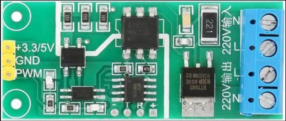
Pulse Width Modulation (PWM) is a versatile technique used to control the amount of power delivered to an electrical device by varying the width of the pulses in a signal. The DEWIN PWM module is a reliable and efficient solution for implementing PWM in various electronic applications. It is commonly used in motor speed control, LED dimming, audio signal generation, and other scenarios requiring precise power or signal control.
Explore Projects Built with PWM
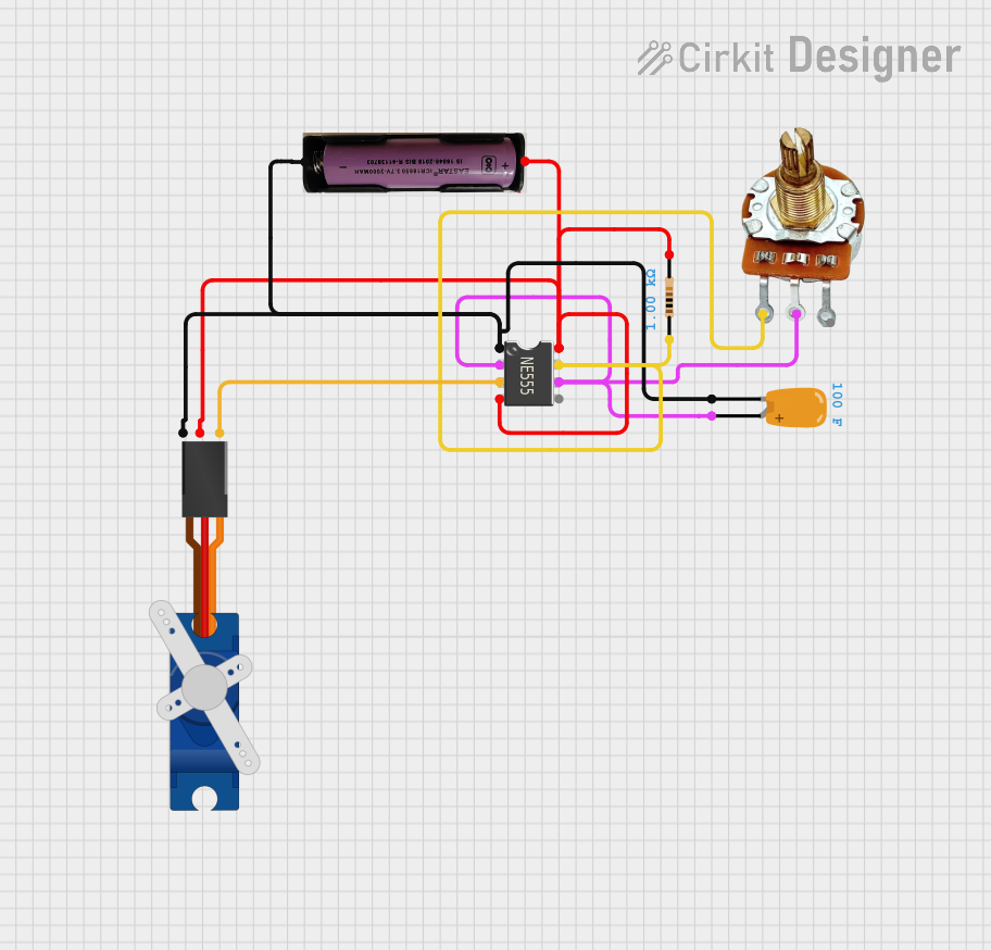

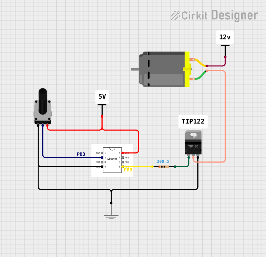

Explore Projects Built with PWM
Common Applications
- Motor Control: Adjusting the speed of DC motors in robotics and industrial systems.
- LED Dimming: Controlling the brightness of LEDs in lighting systems.
- Power Regulation: Managing power delivery in battery chargers and power supplies.
- Audio Applications: Generating audio signals or controlling audio amplifiers.
- Temperature Control: Driving heating elements with precise power levels.
Technical Specifications
The DEWIN PWM module is designed to provide stable and efficient PWM signals for a wide range of applications. Below are the key technical details:
General Specifications
| Parameter | Value |
|---|---|
| Manufacturer | DEWIN |
| Part ID | DEWIN PWM |
| Input Voltage Range | 3.3V to 5V |
| Output Voltage Range | 0V to Input Voltage |
| Frequency Range | 1 Hz to 100 kHz |
| Duty Cycle Range | 0% to 100% |
| Output Current | Up to 20 mA per channel |
| Operating Temperature | -40°C to +85°C |
| Dimensions | 25mm x 15mm x 5mm |
Pin Configuration
The DEWIN PWM module features a simple pinout for easy integration into circuits:
| Pin Number | Pin Name | Description |
|---|---|---|
| 1 | VCC | Power supply input (3.3V to 5V) |
| 2 | GND | Ground connection |
| 3 | PWM_OUT | PWM signal output |
| 4 | CTRL | Control input for adjusting duty cycle or mode |
Usage Instructions
The DEWIN PWM module is straightforward to use in a variety of circuits. Follow the steps below to integrate it into your project:
Basic Circuit Connection
- Power the Module: Connect the
VCCpin to a 3.3V or 5V power source and theGNDpin to the ground of your circuit. - Connect the Output: Use the
PWM_OUTpin to drive your load (e.g., motor, LED, etc.). Ensure the load does not exceed the module's current rating (20 mA). - Control the Duty Cycle: Use the
CTRLpin to adjust the duty cycle. This can be done by connecting it to a microcontroller (e.g., Arduino) or a potentiometer.
Example: Using DEWIN PWM with Arduino UNO
Below is an example of how to use the DEWIN PWM module with an Arduino UNO to control the brightness of an LED:
Circuit Diagram
- Connect
VCCto the Arduino's 5V pin. - Connect
GNDto the Arduino's GND pin. - Connect
PWM_OUTto the LED (with a current-limiting resistor in series). - Connect
CTRLto an Arduino PWM-capable pin (e.g., pin 9).
Arduino Code
// Example code to control DEWIN PWM module with Arduino UNO
// This code gradually increases and decreases the brightness of an LED

const int pwmPin = 9; // Pin connected to DEWIN PWM CTRL pin

void setup() {
  pinMode(pwmPin, OUTPUT); // Set the PWM pin as an output
}

void loop() {
  // Gradually increase brightness
  for (int dutyCycle = 0; dutyCycle <= 255; dutyCycle++) {
    analogWrite(pwmPin, dutyCycle); // Write PWM signal to CTRL pin
    delay(10); // Small delay for smooth transition
  }

  // Gradually decrease brightness
  for (int dutyCycle = 255; dutyCycle >= 0; dutyCycle--) {
    analogWrite(pwmPin, dutyCycle); // Write PWM signal to CTRL pin
    delay(10); // Small delay for smooth transition
  }
}
Important Considerations
- Load Protection: Ensure the connected load does not exceed the module's current rating. Use an external transistor or MOSFET for higher current loads.
- Power Supply: Use a stable power supply to avoid fluctuations in the PWM signal.
- Frequency Adjustment: If the application requires a specific frequency, ensure the microcontroller or external circuit driving the
CTRLpin can generate the desired frequency.
Troubleshooting and FAQs
Common Issues and Solutions
No Output Signal
- Cause: Incorrect power supply connection.
- Solution: Verify that
VCCandGNDare properly connected and within the specified voltage range.
PWM Signal is Unstable
- Cause: Noisy power supply or interference.
- Solution: Use decoupling capacitors (e.g., 0.1 µF) near the power pins to filter noise.
Load Not Responding
- Cause: Load exceeds the module's current rating.
- Solution: Use an external driver circuit (e.g., MOSFET or relay) for high-current loads.
PWM Frequency is Incorrect
- Cause: Improper configuration of the control signal.
- Solution: Check the microcontroller's PWM settings and ensure the frequency matches your requirements.
FAQs
Q1: Can the DEWIN PWM module drive high-power motors directly?
A1: No, the module is limited to 20 mA output current. Use an external driver circuit for high-power motors.
Q2: How do I adjust the frequency of the PWM signal?
A2: The frequency is determined by the control signal applied to the CTRL pin. Use a microcontroller or signal generator to set the desired frequency.
Q3: Is the module compatible with 3.3V systems?
A3: Yes, the DEWIN PWM module operates with input voltages as low as 3.3V, making it compatible with 3.3V systems.
Q4: Can I use the module for audio signal generation?
A4: Yes, the module can generate audio signals within its frequency range (1 Hz to 100 kHz). Ensure the connected load is suitable for audio applications.
By following this documentation, you can effectively integrate the DEWIN PWM module into your projects and achieve precise control over your electronic devices.