How to Use TP5100 4.2V-8.4V: Examples, Pinouts, and Specs
Introduction
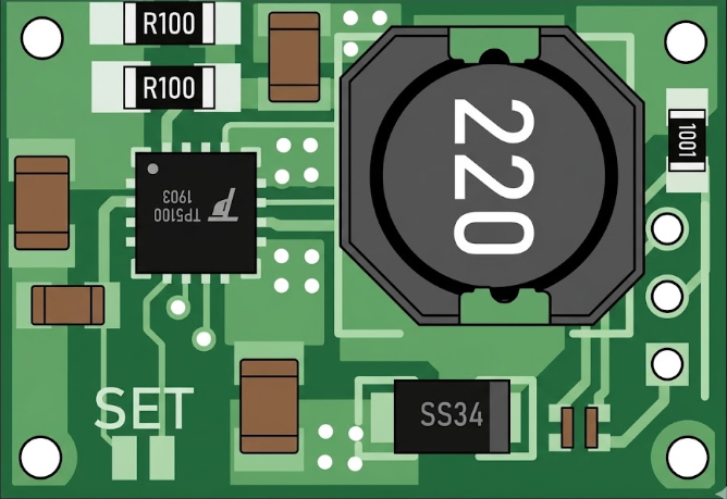
The TP5100 is a lithium battery charger IC designed for charging single-cell or dual-cell lithium-ion batteries with a voltage range of 4.2V to 8.4V. It is a highly efficient charging solution that integrates thermal regulation, overcurrent protection, and short-circuit protection to ensure safe and reliable operation. The TP5100 supports both constant current (CC) and constant voltage (CV) charging modes, making it suitable for a wide range of battery charging applications.
Explore Projects Built with TP5100 4.2V-8.4V


Explore Projects Built with TP5100 4.2V-8.4V
Common Applications
- Lithium-ion battery charging for portable devices
- Power banks and battery packs
- Solar-powered battery chargers
- Embedded systems requiring rechargeable power sources
Technical Specifications
Key Technical Details
| Parameter | Value |
|---|---|
| Input Voltage Range | 5V to 18V |
| Charging Voltage | 4.2V (single-cell) or 8.4V (dual-cell) |
| Charging Current | Up to 2A |
| Efficiency | Up to 90% |
| Operating Temperature Range | -40°C to +85°C |
| Package Type | SOP-8 |
Pin Configuration and Descriptions
| Pin Number | Pin Name | Description |
|---|---|---|
| 1 | VIN | Input voltage pin (5V to 18V). Connect to the power supply. |
| 2 | GND | Ground pin. Connect to the system ground. |
| 3 | BAT | Battery connection pin. Connect to the positive terminal of the battery. |
| 4 | CHRG | Charging status indicator. Low when charging, high when charging is complete. |
| 5 | STDBY | Standby status indicator. High when in standby mode. |
| 6 | ISET | Current setting pin. Connect a resistor to set the charging current. |
| 7 | TEMP | Temperature monitoring pin. Connect to a thermistor for thermal protection. |
| 8 | VCC | Internal power supply pin. Connect a capacitor for stability. |
Usage Instructions
How to Use the TP5100 in a Circuit
- Power Supply: Connect a DC power supply (5V to 18V) to the
VINpin. Ensure the supply voltage matches the battery's charging requirements. - Battery Connection: Connect the positive terminal of the lithium-ion battery to the
BATpin and the negative terminal toGND. - Set Charging Current: Use a resistor on the
ISETpin to configure the desired charging current. The resistor value can be calculated using the formula: [ R_{\text{ISET}} = \frac{1000}{I_{\text{CHARGE}}} ] where ( I_{\text{CHARGE}} ) is the charging current in amperes. - Thermal Protection: Connect a thermistor to the
TEMPpin for temperature monitoring. If not used, connect this pin to ground. - Status Indicators: Use the
CHRGandSTDBYpins to monitor the charging and standby status. These pins can be connected to LEDs for visual indication.
Important Considerations
- Ensure the input voltage does not exceed 18V to avoid damaging the IC.
- Use appropriate decoupling capacitors (e.g., 10µF) on the
VINandVCCpins for stable operation. - Place the IC and associated components on a well-designed PCB with proper thermal management to prevent overheating.
- If using the TP5100 with a dual-cell battery (8.4V), ensure the battery pack includes a balancing circuit for safety.
Example: Using TP5100 with Arduino UNO
The TP5100 can be used with an Arduino UNO to monitor the charging status. Below is an example code snippet:
// Define pin connections for TP5100 status indicators
const int chrgPin = 2;  // CHRG pin connected to Arduino digital pin 2
const int stdbyPin = 3; // STDBY pin connected to Arduino digital pin 3

void setup() {
  pinMode(chrgPin, INPUT);  // Set CHRG pin as input
  pinMode(stdbyPin, INPUT); // Set STDBY pin as input
  Serial.begin(9600);       // Initialize serial communication
}

void loop() {
  int chrgStatus = digitalRead(chrgPin);  // Read CHRG pin status
  int stdbyStatus = digitalRead(stdbyPin); // Read STDBY pin status

  if (chrgStatus == LOW) {
    Serial.println("Battery is charging...");
  } else if (stdbyStatus == HIGH) {
    Serial.println("Battery is fully charged or in standby mode.");
  } else {
    Serial.println("No battery detected or error.");
  }

  delay(1000); // Wait for 1 second before checking again
}
Troubleshooting and FAQs
Common Issues and Solutions
No Charging Current Detected
- Cause: Incorrect resistor value on the
ISETpin. - Solution: Verify the resistor value using the formula ( R_{\text{ISET}} = \frac{1000}{I_{\text{CHARGE}}} ).
- Cause: Incorrect resistor value on the
Overheating of the IC
- Cause: Insufficient thermal dissipation or high ambient temperature.
- Solution: Use a heat sink or improve PCB thermal design. Ensure proper ventilation.
Battery Not Charging
- Cause: Incorrect battery connection or damaged battery.
- Solution: Check the battery polarity and ensure the battery is functional.
Status LEDs Not Working
- Cause: Incorrect connections to the
CHRGorSTDBYpins. - Solution: Verify the connections and ensure the LEDs are functional.
- Cause: Incorrect connections to the
FAQs
Can the TP5100 charge other types of batteries?
- No, the TP5100 is specifically designed for lithium-ion batteries. Using it with other battery chemistries may result in damage or unsafe operation.
What happens if the input voltage exceeds 18V?
- The IC may be permanently damaged. Always ensure the input voltage is within the specified range.
Is it necessary to use the
TEMPpin?- While not mandatory, using the
TEMPpin with a thermistor provides additional safety by monitoring the battery temperature during charging.
- While not mandatory, using the
Can I use the TP5100 for parallel battery configurations?
- Yes, but ensure the batteries are balanced and have the same capacity and charge state to avoid issues.