How to Use MPPT SOLAR CHARGER: Examples, Pinouts, and Specs
Introduction
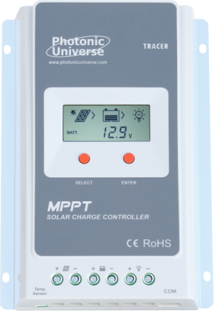
The MPPT Solar Charger, manufactured by Photonics Universe, is a high-efficiency device designed to optimize the power output from solar panels. By employing Maximum Power Point Tracking (MPPT) technology, this charger dynamically adjusts the electrical operating point of the solar panels to ensure maximum energy harvest. It is particularly effective in varying sunlight conditions, making it an essential component for solar energy systems.
Explore Projects Built with MPPT SOLAR CHARGER
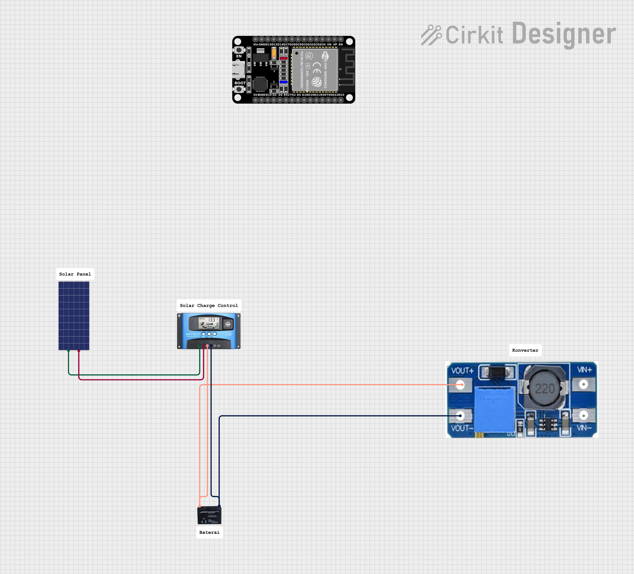
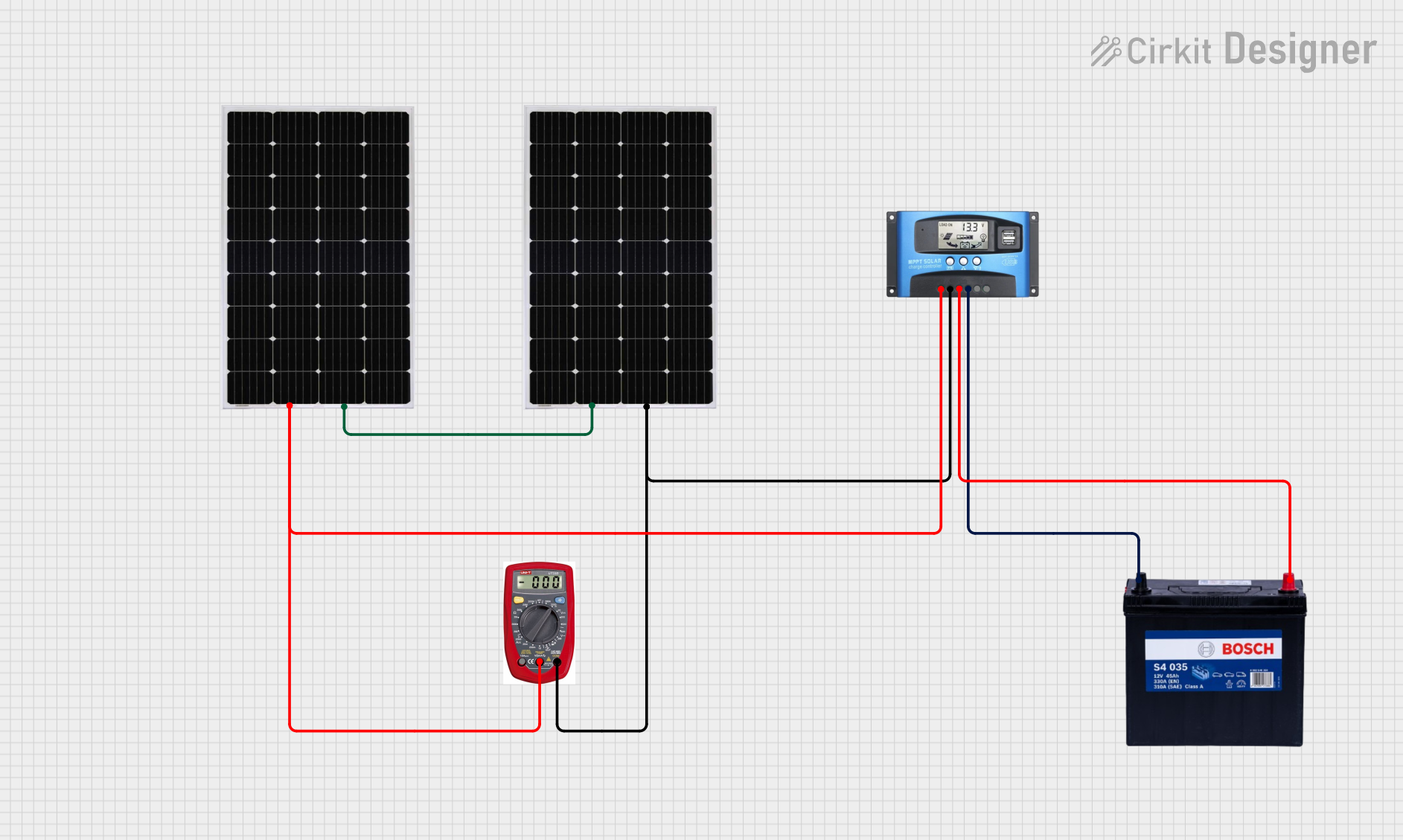
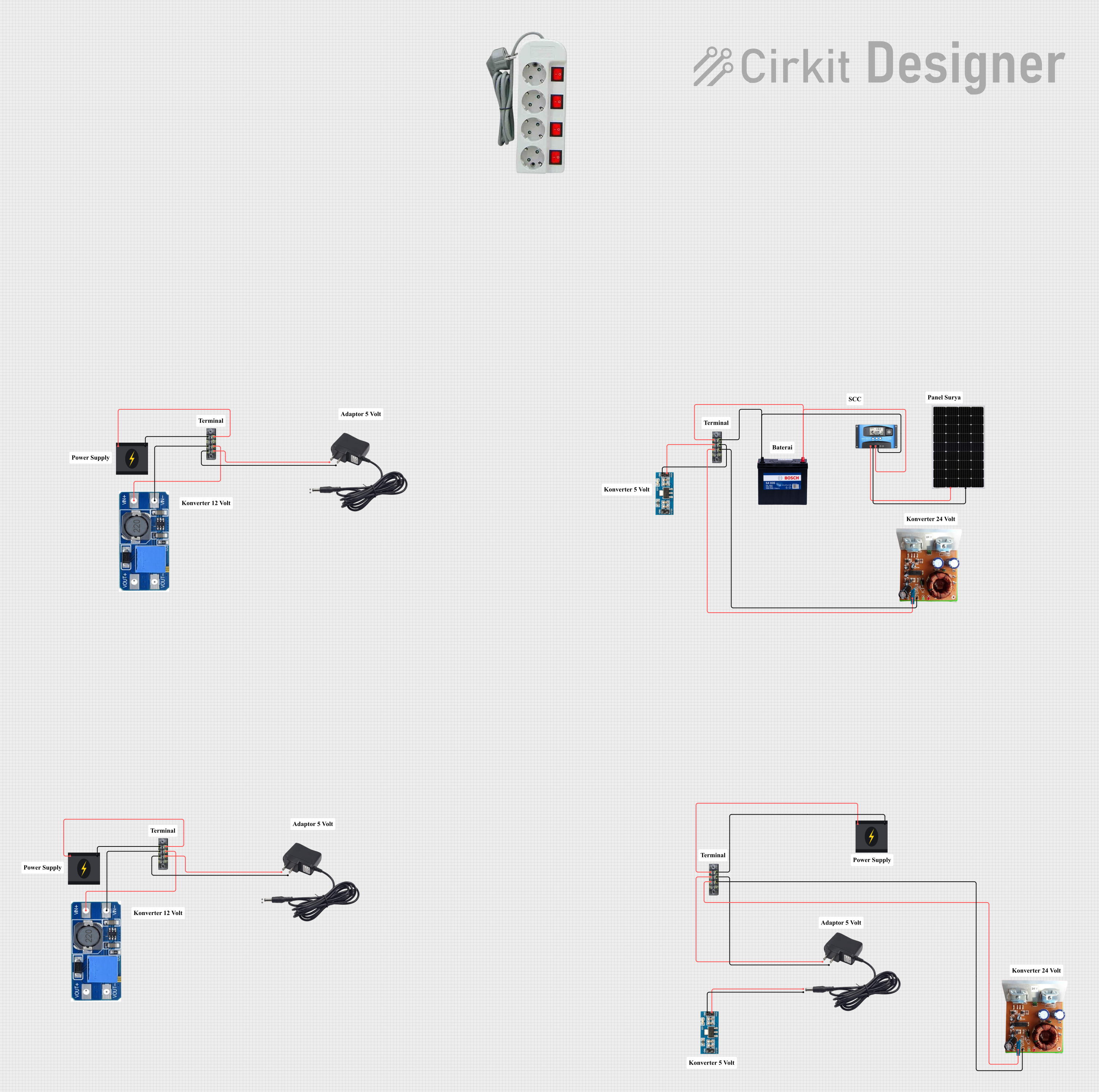
Explore Projects Built with MPPT SOLAR CHARGER
Common Applications and Use Cases
- Off-grid solar power systems
- Residential and commercial solar installations
- RVs, boats, and other mobile solar setups
- Battery charging for lead-acid, lithium-ion, and other battery types
- Solar-powered lighting and remote monitoring systems
Technical Specifications
Below are the key technical details of the MPPT Solar Charger:
| Parameter | Value |
|---|---|
| Input Voltage Range | 12V to 100V DC |
| Output Voltage Range | 12V/24V/48V (auto or manual selection) |
| Maximum Input Power | 390W (12V system), 780W (24V system), |
| 1560W (48V system) | |
| Maximum Charging Current | 40A |
| Efficiency | Up to 98% |
| Battery Compatibility | Lead-acid (AGM, Gel, Flooded), Lithium-ion |
| Operating Temperature Range | -20°C to +60°C |
| Communication Interface | RS485, optional Bluetooth module |
| Protection Features | Overcharge, over-discharge, short circuit, |
| reverse polarity, over-temperature |
Pin Configuration and Descriptions
The MPPT Solar Charger typically features the following input/output terminals:
| Pin/Terminal | Description |
|---|---|
| PV+ | Positive terminal for solar panel input |
| PV- | Negative terminal for solar panel input |
| BAT+ | Positive terminal for battery connection |
| BAT- | Negative terminal for battery connection |
| LOAD+ | Positive terminal for DC load connection (optional) |
| LOAD- | Negative terminal for DC load connection (optional) |
| RS485+ | Positive terminal for RS485 communication |
| RS485- | Negative terminal for RS485 communication |
Usage Instructions
How to Use the MPPT Solar Charger in a Circuit
Connect the Solar Panel:
- Connect the positive (+) and negative (-) terminals of the solar panel to the PV+ and PV- inputs on the charger.
- Ensure the solar panel's voltage is within the charger's input voltage range.
Connect the Battery:
- Attach the positive (+) and negative (-) terminals of the battery to the BAT+ and BAT- outputs on the charger.
- Verify that the battery type is compatible with the charger.
Optional Load Connection:
- If powering a DC load directly, connect the load's positive (+) and negative (-) terminals to the LOAD+ and LOAD- outputs.
Power On:
- Once all connections are secure, the charger will automatically detect the system voltage and begin operation.
Monitor and Adjust Settings:
- Use the built-in display or communication interface (e.g., RS485 or Bluetooth) to monitor performance and adjust settings as needed.
Important Considerations and Best Practices
- System Voltage: Ensure the solar panel and battery voltages are compatible with the charger's operating range.
- Wiring: Use appropriately rated cables to handle the current and minimize voltage drops.
- Ventilation: Install the charger in a well-ventilated area to prevent overheating.
- Fuses and Circuit Breakers: Add fuses or circuit breakers on the input and output lines for additional protection.
- Firmware Updates: Check for firmware updates from Photonics Universe to ensure optimal performance.
Arduino UNO Integration Example
The MPPT Solar Charger can be monitored using an Arduino UNO via the RS485 interface. Below is an example code snippet for reading data from the charger:
#include <SoftwareSerial.h>

// Define RS485 communication pins
#define RX_PIN 10  // Arduino pin connected to RS485 module's RO (Receive Out)
#define TX_PIN 11  // Arduino pin connected to RS485 module's DI (Data In)
#define DE_PIN 9   // Arduino pin connected to RS485 module's DE (Driver Enable)
#define RE_PIN 8   // Arduino pin connected to RS485 module's RE (Receiver Enable)

SoftwareSerial rs485Serial(RX_PIN, TX_PIN);

void setup() {
  pinMode(DE_PIN, OUTPUT);
  pinMode(RE_PIN, OUTPUT);

  // Initialize RS485 communication
  digitalWrite(DE_PIN, LOW);  // Disable driver
  digitalWrite(RE_PIN, LOW);  // Enable receiver
  rs485Serial.begin(9600);   // Set baud rate for RS485 communication

  Serial.begin(9600);        // Set baud rate for serial monitor
  Serial.println("MPPT Solar Charger Monitoring Initialized");
}

void loop() {
  // Request data from MPPT charger
  digitalWrite(DE_PIN, HIGH);  // Enable driver
  digitalWrite(RE_PIN, HIGH);  // Disable receiver
  rs485Serial.write(0x01);     // Example request command (modify as needed)
  delay(10);
  digitalWrite(DE_PIN, LOW);   // Disable driver
  digitalWrite(RE_PIN, LOW);   // Enable receiver

  // Read response from MPPT charger
  if (rs485Serial.available()) {
    Serial.print("Data from MPPT Charger: ");
    while (rs485Serial.available()) {
      Serial.print(rs485Serial.read(), HEX);
      Serial.print(" ");
    }
    Serial.println();
  }

  delay(1000);  // Wait 1 second before next request
}
Notes:
- Replace the example request command (
0x01) with the appropriate command for your MPPT Solar Charger. - Ensure the RS485 module is correctly connected to the Arduino and the MPPT charger.
Troubleshooting and FAQs
Common Issues and Solutions
Charger Not Powering On:
- Verify that the solar panel and battery are properly connected.
- Check for blown fuses or tripped circuit breakers.
Low Charging Efficiency:
- Ensure the solar panel is receiving adequate sunlight.
- Check for loose or corroded connections.
Overheating:
- Install the charger in a well-ventilated area.
- Reduce the load or input power if operating near the maximum limits.
Communication Issues with RS485:
- Verify the wiring between the RS485 module and the charger.
- Ensure the baud rate and communication settings match.
FAQs
Q: Can I use this charger with a 36V battery system?
A: No, the charger supports 12V, 24V, and 48V systems only.
Q: Does the charger work during cloudy weather?
A: Yes, the MPPT technology optimizes power output even in low-light conditions.
Q: How do I update the firmware?
A: Refer to the Photonics Universe website or user manual for firmware update instructions.
Q: Can I connect multiple solar panels?
A: Yes, but ensure the combined voltage and current are within the charger's input limits.