How to Use Autoro Dual DV6.7: Examples, Pinouts, and Specs
Introduction
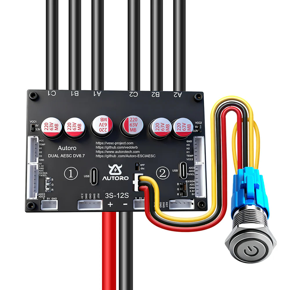
The Autoro Dual DV6.7 is a dual-channel digital voltmeter designed for accurate and reliable voltage measurements. With its clear display and adjustable settings, it is ideal for a wide range of applications, including laboratory experiments, field diagnostics, and electronic circuit testing. Its dual-channel capability allows users to measure two voltage sources simultaneously, making it a versatile tool for professionals and hobbyists alike.
Explore Projects Built with Autoro Dual DV6.7
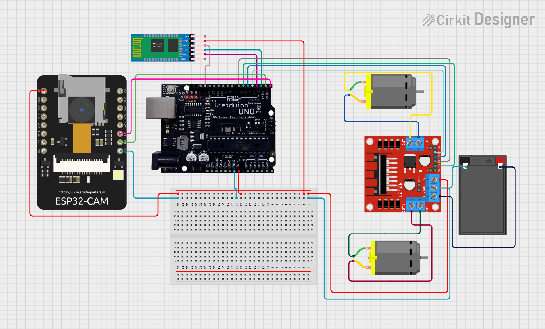
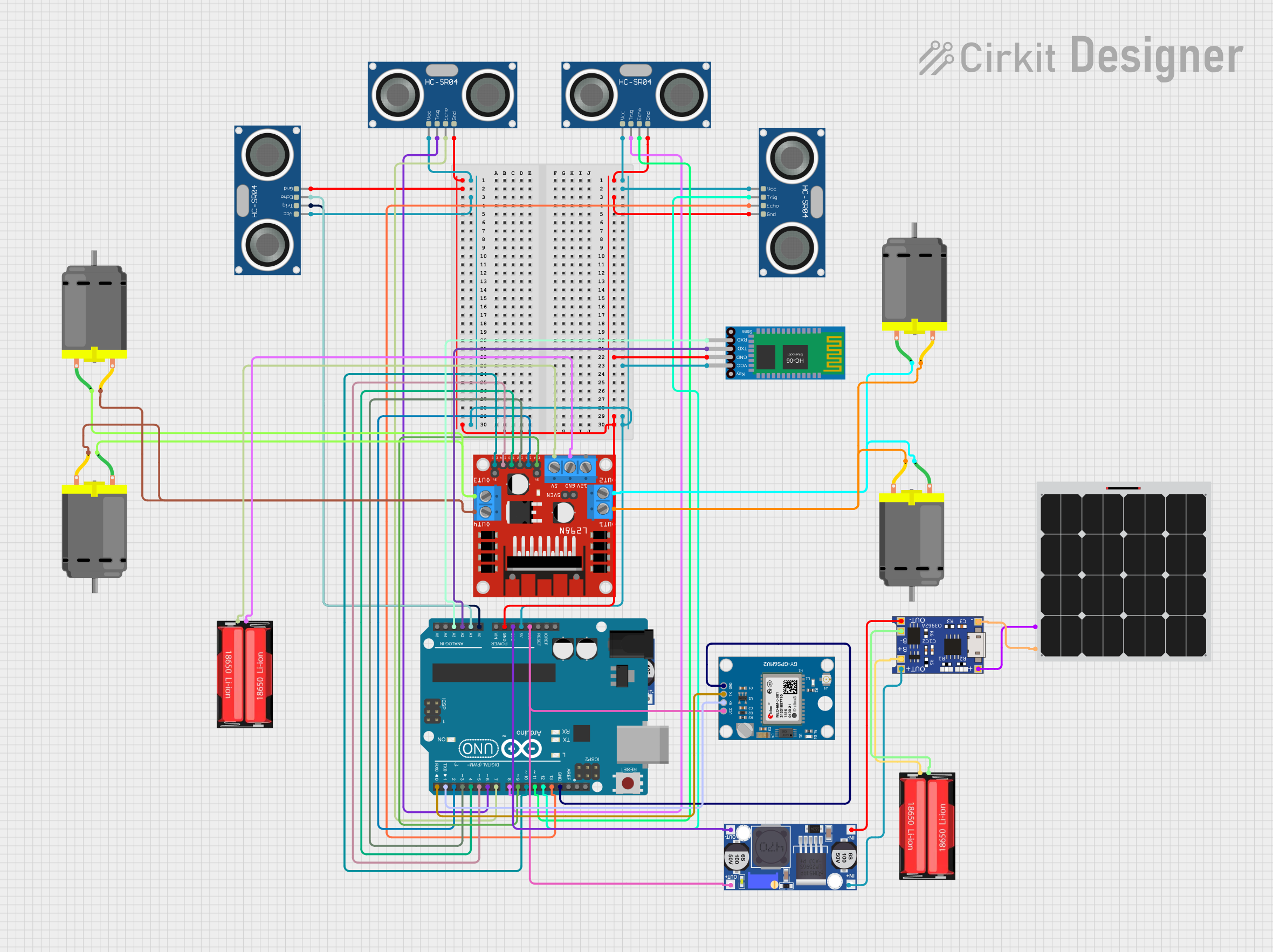
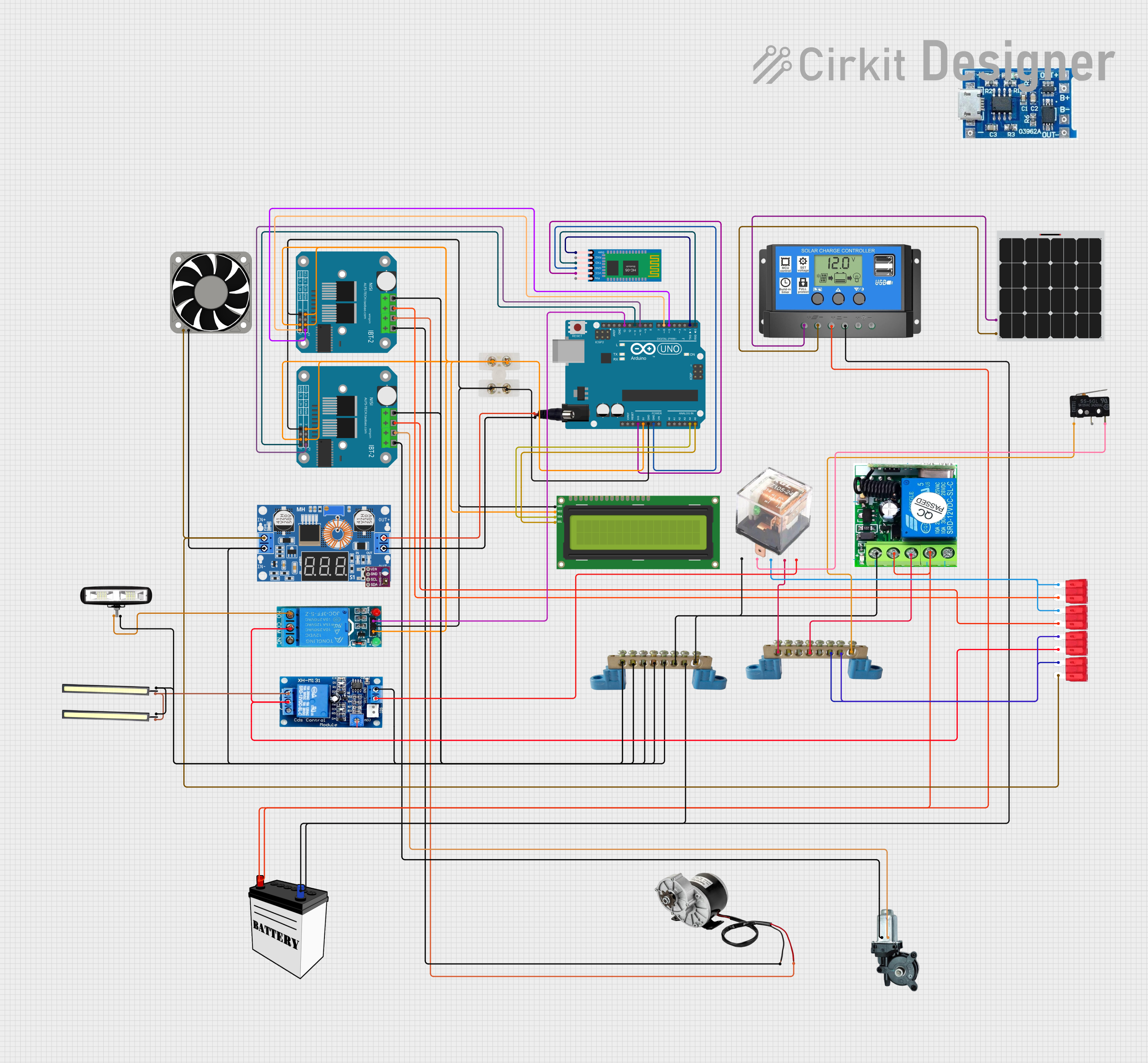

Explore Projects Built with Autoro Dual DV6.7
Common Applications and Use Cases
- Laboratory voltage measurements for research and development
- Field diagnostics for electrical systems and equipment
- Testing and troubleshooting electronic circuits
- Educational purposes in electronics and engineering courses
- Monitoring power supplies in real-time
Technical Specifications
Key Technical Details
| Parameter | Specification |
|---|---|
| Input Voltage Range | 0 - 100 V DC |
| Measurement Accuracy | ±0.5% |
| Display Type | Dual 7-segment LED |
| Display Resolution | 0.01 V |
| Power Supply Voltage | 5 V DC |
| Power Consumption | < 200 mW |
| Operating Temperature | -10°C to 50°C |
| Dimensions | 80 mm x 40 mm x 25 mm |
| Weight | 50 g |
Pin Configuration and Descriptions
The Autoro Dual DV6.7 has a 6-pin interface for power and signal connections. The table below describes each pin:
| Pin Number | Pin Name | Description |
|---|---|---|
| 1 | VCC | Power supply input (5 V DC) |
| 2 | GND | Ground connection |
| 3 | CH1+ | Positive input for Channel 1 voltage measurement |
| 4 | CH1- | Negative input for Channel 1 voltage measurement |
| 5 | CH2+ | Positive input for Channel 2 voltage measurement |
| 6 | CH2- | Negative input for Channel 2 voltage measurement |
Usage Instructions
How to Use the Component in a Circuit
- Power the Device: Connect the
VCCpin to a 5 V DC power source and theGNDpin to ground. - Connect Voltage Sources:
- For Channel 1, connect the positive terminal of the voltage source to
CH1+and the negative terminal toCH1-. - For Channel 2, connect the positive terminal of the voltage source to
CH2+and the negative terminal toCH2-.
- For Channel 1, connect the positive terminal of the voltage source to
- Read the Display: The dual 7-segment LED display will show the voltage readings for both channels simultaneously.
Important Considerations and Best Practices
- Ensure the input voltage does not exceed the maximum range of 100 V DC to avoid damage.
- Use proper grounding to minimize noise and ensure accurate measurements.
- Avoid exposing the device to extreme temperatures or humidity.
- If using the voltmeter with an Arduino UNO or similar microcontroller, ensure the power supply is stable and within the specified range.
Example: Connecting to an Arduino UNO
The Autoro Dual DV6.7 can be used with an Arduino UNO to monitor voltage readings programmatically. Below is an example code snippet:
// Example code to read voltage from Autoro Dual DV6.7 using Arduino UNO
// Note: This assumes the voltmeter outputs analog signals for voltage readings.

const int ch1Pin = A0; // Channel 1 connected to analog pin A0
const int ch2Pin = A1; // Channel 2 connected to analog pin A1

void setup() {
  Serial.begin(9600); // Initialize serial communication at 9600 baud
}

void loop() {
  // Read analog values from both channels
  int ch1Value = analogRead(ch1Pin);
  int ch2Value = analogRead(ch2Pin);

  // Convert analog values to voltage (assuming 5V reference and 10-bit ADC)
  float ch1Voltage = (ch1Value / 1023.0) * 5.0;
  float ch2Voltage = (ch2Value / 1023.0) * 5.0;

  // Print the voltage readings to the Serial Monitor
  Serial.print("Channel 1 Voltage: ");
  Serial.print(ch1Voltage);
  Serial.println(" V");

  Serial.print("Channel 2 Voltage: ");
  Serial.print(ch2Voltage);
  Serial.println(" V");

  delay(1000); // Wait for 1 second before the next reading
}
Troubleshooting and FAQs
Common Issues and Solutions
No Display or Incorrect Readings:
- Ensure the power supply is connected properly and provides 5 V DC.
- Verify that the input voltage is within the specified range (0 - 100 V DC).
- Check for loose or incorrect wiring connections.
Flickering or Dim Display:
- Confirm that the power supply can provide sufficient current (at least 50 mA).
- Avoid using long or thin wires for the power supply, as this can cause voltage drops.
Inaccurate Measurements:
- Ensure proper grounding to reduce noise interference.
- Use shielded cables for input connections if operating in a noisy environment.
Device Overheating:
- Check that the operating temperature is within the specified range (-10°C to 50°C).
- Avoid placing the device near heat sources or in direct sunlight.
Frequently Asked Questions
Q: Can the Autoro Dual DV6.7 measure AC voltage?
A: No, the device is designed for DC voltage measurements only.
Q: Is it possible to calibrate the voltmeter?
A: The device is factory-calibrated for accuracy. If recalibration is needed, contact Autoro support.
Q: Can I use the voltmeter with a 3.3 V power supply?
A: No, the device requires a 5 V DC power supply for proper operation.
Q: What happens if the input voltage exceeds 100 V DC?
A: Exceeding the maximum input voltage may damage the device permanently. Always ensure the input voltage is within the specified range.