How to Use 1933 Telephone: Examples, Pinouts, and Specs
Introduction
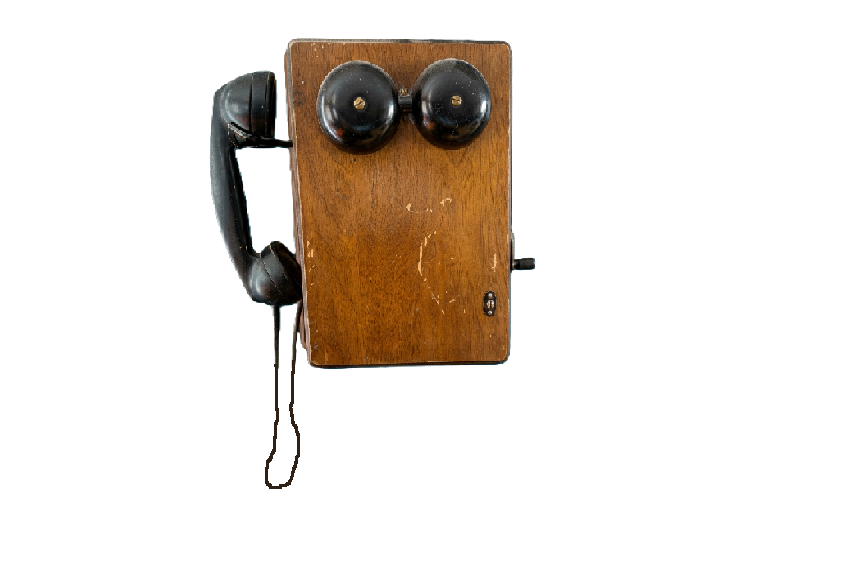
The 1933 Telephone is a vintage communication device renowned for its rotary dial mechanism and iconic design. It was a pivotal innovation in telecommunication, enabling voice communication over long distances through analog signal transmission. This model is a collector's item today and is often repurposed for decorative purposes or retrofitted for modern use.
Explore Projects Built with 1933 Telephone
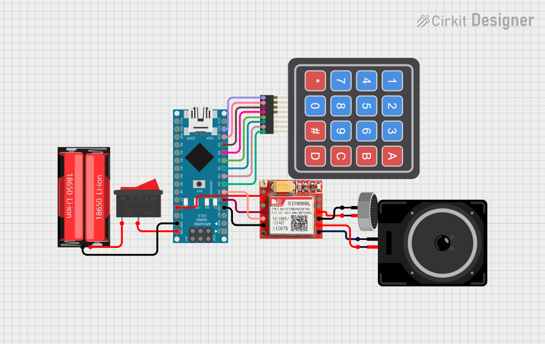
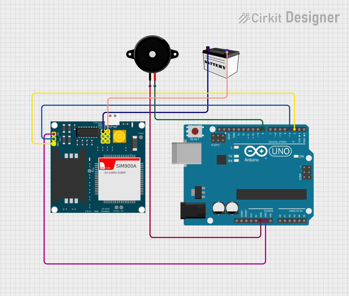
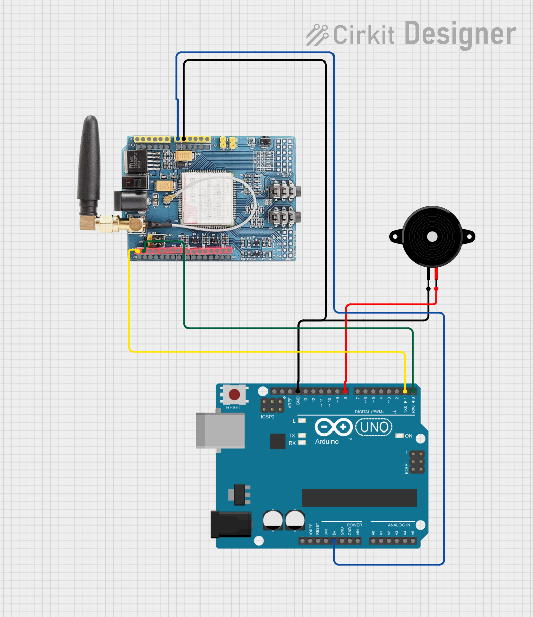
Explore Projects Built with 1933 Telephone
Common Applications and Use Cases
- Historical Collectibles: Preserved as a piece of telecommunication history.
- Home Decor: Used as a vintage decorative item in homes and offices.
- Retrofit Projects: Modified to work with modern telecommunication systems or as a novelty item.
- Educational Demonstrations: Used to teach the basics of analog telecommunication.
Technical Specifications
Key Technical Details
- Year of Manufacture: 1933
- Dial Type: Rotary dial with mechanical pulse signaling
- Material: Bakelite or metal (varies by manufacturer)
- Power Source: Passive device powered by the telephone exchange
- Connectivity: Two-wire analog connection
- Audio Transmission: Analog voice signals
- Ringer Type: Mechanical bell with an internal striker mechanism
Pin Configuration and Descriptions
The 1933 Telephone uses a two-wire analog connection. Below is a description of the wiring:
| Pin/Terminal | Description |
|---|---|
| Line 1 (L1) | Connects to the positive terminal of the telephone line. |
| Line 2 (L2) | Connects to the negative terminal of the telephone line. |
Usage Instructions
How to Use the 1933 Telephone
Connecting to a Telephone Line:
- Identify the two terminals (L1 and L2) on the telephone.
- Connect L1 and L2 to the corresponding terminals of an analog telephone line.
- Ensure the line provides the required voltage and current for operation (typically 48V DC for traditional systems).
Making a Call:
- Lift the handset to activate the line.
- Rotate the rotary dial to input the desired phone number. Each number is dialed by turning the dial to the corresponding digit and releasing it.
- Wait for the call to connect and begin speaking once the recipient answers.
Receiving a Call:
- When the telephone rings, lift the handset to answer the call.
- Speak into the mouthpiece and listen through the earpiece.
Important Considerations and Best Practices
- Line Compatibility: Ensure the telephone line supports analog pulse dialing. Modern digital systems may require a pulse-to-tone converter.
- Maintenance: Regularly clean the rotary dial and internal components to ensure smooth operation.
- Voltage Safety: Avoid connecting the telephone to lines with voltages exceeding the standard 48V DC to prevent damage.
- Retrofit Projects: If retrofitting for modern use, consult a professional to integrate tone dialing or VoIP adapters.
Arduino Integration
While the 1933 Telephone is not inherently compatible with microcontrollers like the Arduino UNO, it can be retrofitted for experimental purposes. For example, you can use an Arduino to detect the rotary dial pulses. Below is a sample code snippet for detecting pulses:
// Rotary Dial Pulse Detection with Arduino
const int pulsePin = 2; // Pin connected to the rotary dial pulse output
int pulseCount = 0;     // Variable to store the pulse count

void setup() {
  pinMode(pulsePin, INPUT_PULLUP); // Set pulsePin as input with pull-up resistor
  Serial.begin(9600);             // Initialize serial communication
}

void loop() {
  static int lastState = HIGH; // Store the last state of the pulse pin
  int currentState = digitalRead(pulsePin); // Read the current state

  // Detect falling edge (HIGH to LOW transition)
  if (lastState == HIGH && currentState == LOW) {
    pulseCount++; // Increment pulse count
    Serial.print("Pulse detected! Total pulses: ");
    Serial.println(pulseCount); // Print pulse count to serial monitor
  }

  lastState = currentState; // Update lastState
}
Troubleshooting and FAQs
Common Issues and Solutions
No Dial Tone:
- Cause: The telephone is not connected to a compatible line.
- Solution: Verify the connection to an analog telephone line and ensure proper wiring.
Rotary Dial Sticking:
- Cause: Dust or debris in the rotary mechanism.
- Solution: Clean the rotary dial with a soft cloth and apply a small amount of lubricant to the moving parts.
No Ringing:
- Cause: Faulty ringer mechanism or insufficient line voltage.
- Solution: Check the ringer mechanism for damage and ensure the line provides adequate voltage.
Pulse Dialing Not Recognized:
- Cause: Modern telephone systems may not support pulse dialing.
- Solution: Use a pulse-to-tone converter to enable compatibility with modern systems.
FAQs
Can the 1933 Telephone be used with modern VoIP systems?
- Yes, but it requires a VoIP adapter and possibly a pulse-to-tone converter.
How do I clean and maintain the telephone?
- Use a soft, damp cloth to clean the exterior. For internal components, consult a professional to avoid damage.
Is it possible to replace the rotary dial with a modern keypad?
- Yes, but this requires significant modification and may reduce the historical value of the telephone.
Can I use the 1933 Telephone as a decorative item without connecting it?
- Absolutely! It makes an excellent vintage decor piece even without functional connectivity.