
How to Use DPAC WiFi Module: Examples, Pinouts, and Specs
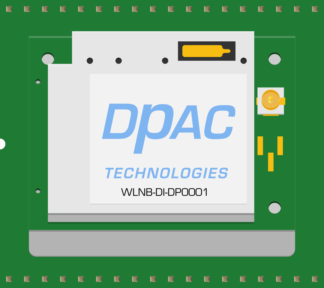
 Design with DPAC WiFi Module in Cirkit Designer
Introduction
The DPAC WiFi Module is a compact and versatile electronic component designed to enable wireless connectivity for a wide range of devices. It allows devices to connect to WiFi networks for seamless data transmission and communication. This module is ideal for IoT applications, smart home devices, industrial automation, and other projects requiring reliable wireless communication.
Explore Projects Built with DPAC WiFi Module
 Open Project in Cirkit Designer
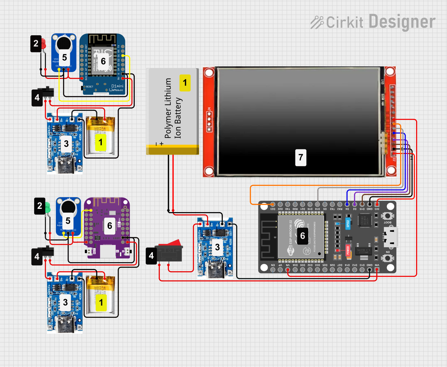 Open Project in Cirkit Designer
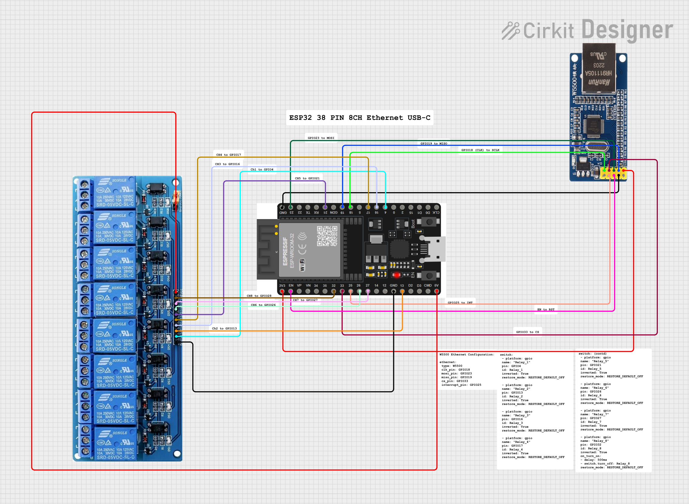 Open Project in Cirkit Designer
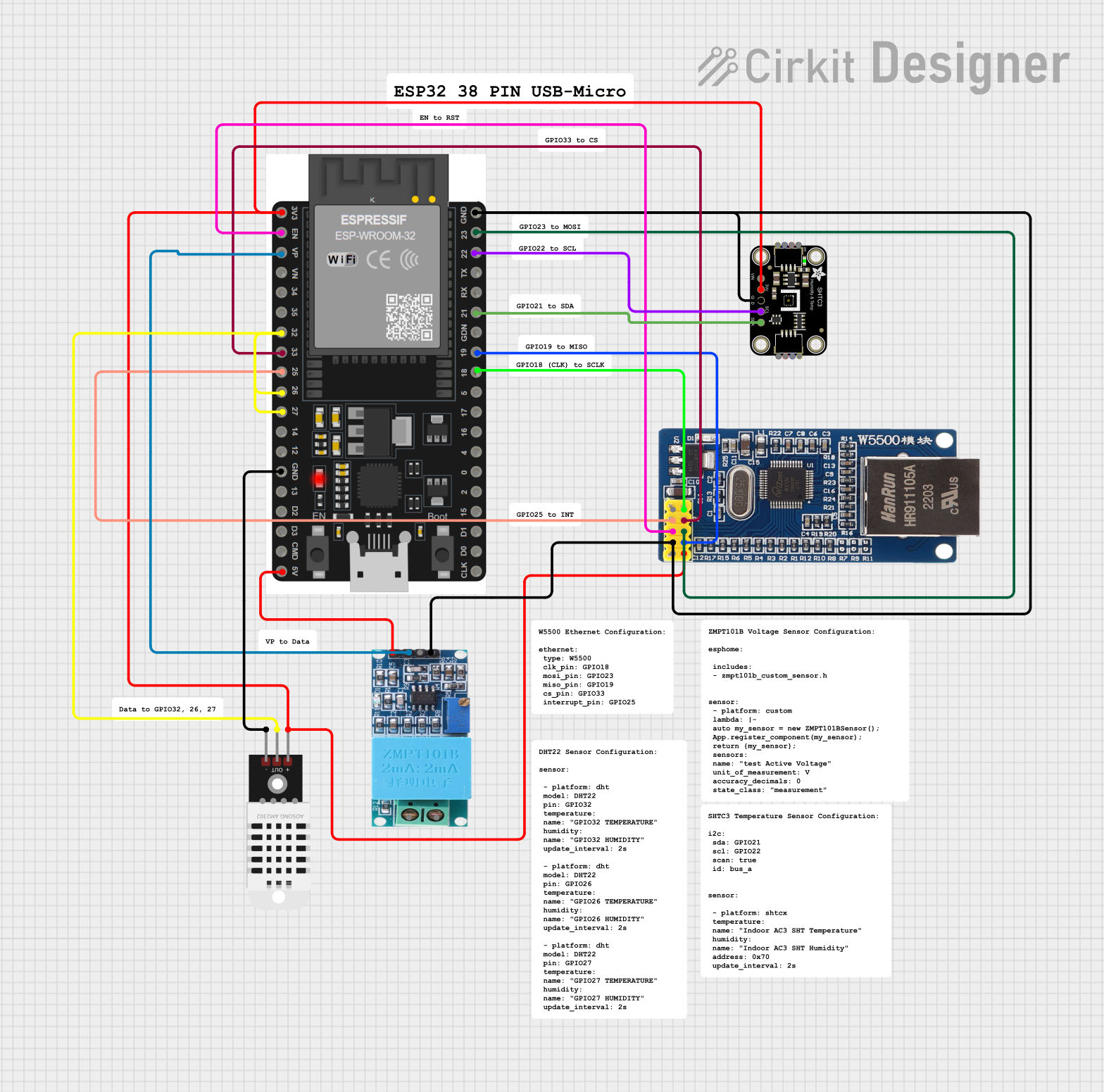 Open Project in Cirkit Designer
Explore Projects Built with DPAC WiFi Module
Open Project in Cirkit DesignerOpen Project in Cirkit DesignerOpen Project in Cirkit DesignerOpen Project in Cirkit DesignerCommon Applications and Use Cases
- Internet of Things (IoT) devices
- Smart home automation systems
- Wireless sensor networks
- Industrial monitoring and control
- Remote data logging and telemetry
- Embedded systems requiring WiFi connectivity
Technical Specifications
The DPAC WiFi Module is designed to provide robust wireless communication with low power consumption. Below are its key technical specifications:
| Parameter | Value |
|---|---|
| Operating Voltage | 3.3V |
| Current Consumption | 80mA (active), 10µA (standby) |
| Wireless Standard | IEEE 802.11 b/g/n |
| Frequency Range | 2.4 GHz |
| Data Rate | Up to 150 Mbps |
| Security Protocols | WPA/WPA2, WEP, TKIP, AES |
| Operating Temperature | -40°C to 85°C |
| Dimensions | 25mm x 15mm x 3mm |
Pin Configuration and Descriptions
The DPAC WiFi Module features a standard pinout for easy integration into circuits. Below is the pin configuration:
| Pin Number | Pin Name | Description |
|---|---|---|
| 1 | VCC | Power supply input (3.3V) |
| 2 | GND | Ground connection |
| 3 | TX | UART Transmit pin for serial communication |
| 4 | RX | UART Receive pin for serial communication |
| 5 | EN | Enable pin (active HIGH to power on the module) |
| 6 | GPIO0 | General-purpose I/O pin |
| 7 | GPIO1 | General-purpose I/O pin |
| 8 | RESET | Reset pin (active LOW to reset the module) |
| 9 | ANT | External antenna connection |
Usage Instructions
How to Use the DPAC WiFi Module in a Circuit
- Power Supply: Connect the VCC pin to a 3.3V power source and the GND pin to ground.
- Serial Communication: Use the TX and RX pins to interface with a microcontroller or computer via UART.
- Enable the Module: Pull the EN pin HIGH to activate the module.
- Antenna Connection: For better signal strength, connect an external antenna to the ANT pin.
- Reset: Use the RESET pin to restart the module if needed.
Important Considerations and Best Practices
- Ensure the power supply is stable and within the specified 3.3V range to avoid damaging the module.
- Use level shifters if interfacing with a 5V microcontroller to prevent overvoltage on the UART pins.
- Place the module away from high-frequency noise sources to maintain signal integrity.
- Use proper decoupling capacitors near the VCC pin to filter out power supply noise.
Example: Connecting the DPAC WiFi Module to an Arduino UNO
The DPAC WiFi Module can be easily connected to an Arduino UNO for wireless communication. Below is an example wiring diagram and code:
Wiring Diagram
| DPAC Pin | Arduino Pin |
|---|---|
| VCC | 3.3V |
| GND | GND |
| TX | Pin 10 (RX) |
| RX | Pin 11 (TX) |
| EN | 3.3V |
| RESET | Digital Pin 8 |
Arduino Code Example
#include <SoftwareSerial.h>

// Define RX and TX pins for SoftwareSerial
SoftwareSerial wifiModule(10, 11); // RX = Pin 10, TX = Pin 11

void setup() {
  // Initialize serial communication with the WiFi module
  wifiModule.begin(9600);
  Serial.begin(9600); // For debugging via Serial Monitor

  // Enable the WiFi module
  pinMode(8, OUTPUT); // Set RESET pin as output
  digitalWrite(8, HIGH); // Pull RESET pin HIGH to enable the module

  Serial.println("Initializing DPAC WiFi Module...");
  delay(2000); // Wait for the module to initialize

  // Send a test command to the module
  wifiModule.println("AT"); // Send AT command to check communication
}

void loop() {
  // Check for data from the WiFi module
  if (wifiModule.available()) {
    String response = wifiModule.readString();
    Serial.println("WiFi Module Response: " + response);
  }

  // Check for user input from Serial Monitor
  if (Serial.available()) {
    String command = Serial.readString();
    wifiModule.println(command); // Send user command to WiFi module
  }
}
Troubleshooting and FAQs
Common Issues and Solutions
Module Not Responding to Commands
- Ensure the EN pin is pulled HIGH to activate the module.
- Verify the power supply is stable and within the 3.3V range.
- Check the UART connections (TX and RX) for proper wiring.
Poor WiFi Signal Strength
- Use an external antenna for better signal reception.
- Avoid placing the module near metal objects or other RF sources.
Overheating
- Ensure proper ventilation and avoid exceeding the operating temperature range.
- Check for short circuits or excessive current draw in the circuit.
Communication Errors
- Verify the baud rate settings in your code match the module's default baud rate.
- Use shorter wires for UART connections to reduce signal degradation.
FAQs
Q: Can the DPAC WiFi Module operate on 5V?
A: No, the module operates at 3.3V. Using 5V can damage the module. Use a voltage regulator or level shifter if necessary.
Q: How do I reset the module?
A: Pull the RESET pin LOW momentarily and then HIGH to restart the module.
Q: What is the default baud rate of the module?
A: The default baud rate is 9600 bps. You can change it using AT commands.
Q: Can I use the module without an external antenna?
A: Yes, but using an external antenna improves signal strength and range significantly.