How to Use ATS 3phase: Examples, Pinouts, and Specs
Introduction
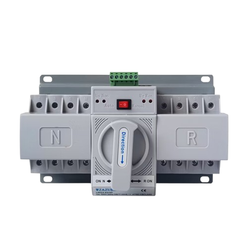
An Automatic Transfer Switch (ATS) for three-phase power systems is a critical component in ensuring uninterrupted power supply. It automatically switches between a primary power source (e.g., utility grid) and a backup power source (e.g., generator) in the event of a power failure or instability in the primary source. This ensures that connected equipment continues to operate without interruption.
Explore Projects Built with ATS 3phase


Explore Projects Built with ATS 3phase
Common Applications and Use Cases
- Industrial facilities requiring continuous power for machinery and operations.
- Data centers to maintain uptime for servers and critical IT infrastructure.
- Hospitals and healthcare facilities to ensure life-support systems remain operational.
- Commercial buildings and offices for uninterrupted lighting and HVAC systems.
- Residential buildings with backup generators for emergency power.
Technical Specifications
Key Technical Details
- Voltage Rating: 380V AC (three-phase)
- Current Rating: 63A, 100A, 160A, 250A, 400A (varies by model)
- Frequency: 50Hz/60Hz
- Switching Time: ≤3 seconds (typical)
- Control Voltage: 220V AC or 24V DC (depending on model)
- Operating Temperature: -20°C to 60°C
- Enclosure Protection: IP30 to IP65 (model-dependent)
- Mechanical Life: ≥10,000 cycles
- Electrical Life: ≥5,000 cycles
Pin Configuration and Descriptions
The ATS 3phase typically has terminals for connecting the primary power source, backup power source, and load. Below is a general pin configuration:
| Pin/Terminal | Description |
|---|---|
| L1, L2, L3 (Primary) | Input terminals for the primary power source (three-phase). |
| L1, L2, L3 (Backup) | Input terminals for the backup power source (three-phase). |
| N (Neutral) | Neutral connection for both primary and backup sources. |
| PE (Protective Earth) | Grounding terminal for safety. |
| Load L1, L2, L3 | Output terminals to connect the load (three-phase). |
| Control Input | Terminals for control signals (e.g., start/stop generator). |
| Status Output | Terminals for status feedback (e.g., active source). |
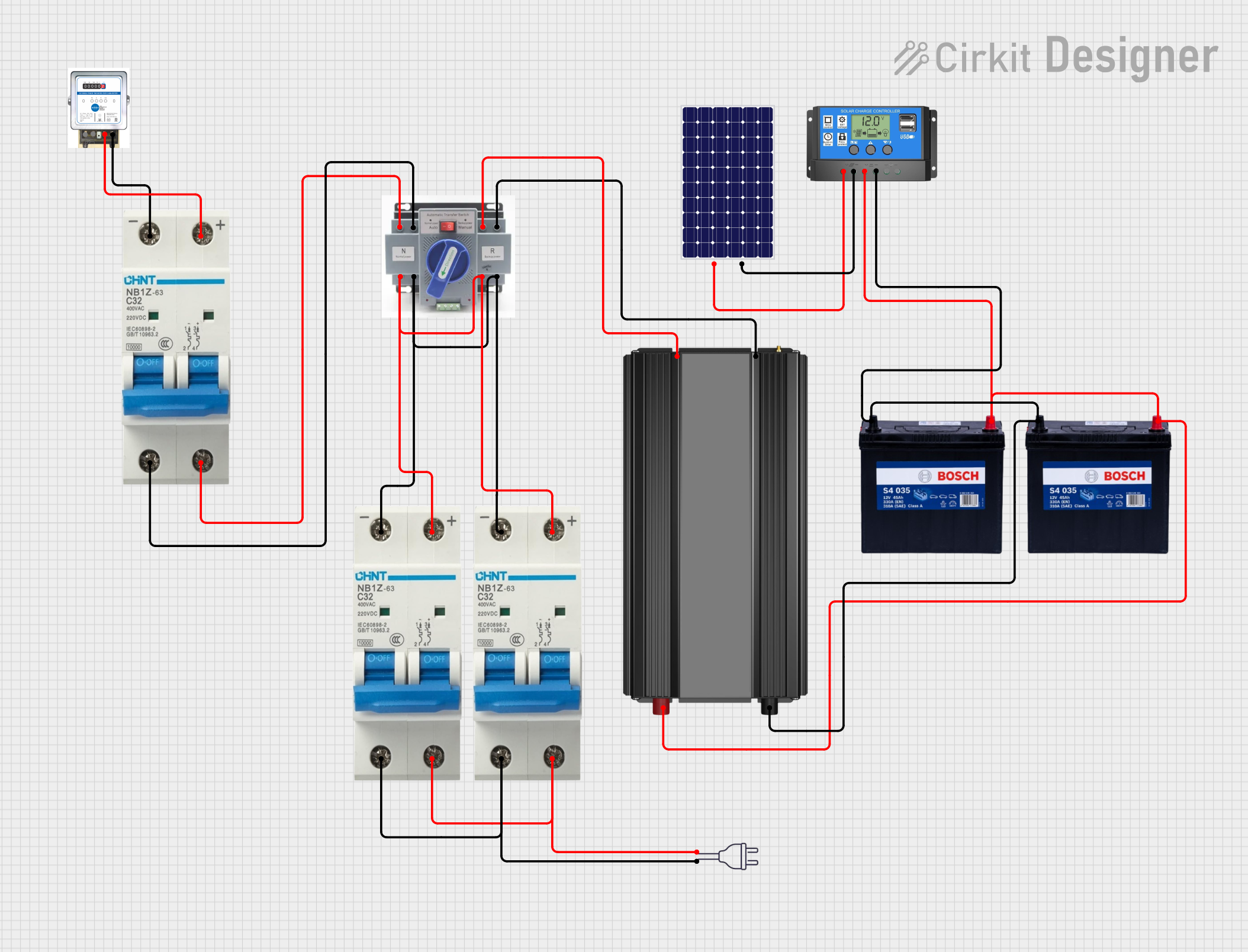
Usage Instructions
How to Use the Component in a Circuit
Installation:
- Ensure the ATS is rated for the voltage and current of your system.
- Mount the ATS in a secure location with adequate ventilation.
- Connect the primary power source (utility grid) to the designated input terminals (L1, L2, L3).
- Connect the backup power source (generator) to the backup input terminals (L1, L2, L3).
- Connect the load to the output terminals (Load L1, L2, L3).
- Connect the neutral (N) and protective earth (PE) terminals.
Control Wiring:
- If the ATS supports generator start/stop control, connect the control wires to the generator.
- Configure the control voltage (e.g., 220V AC or 24V DC) as per the ATS model.
Testing:
- Power on the primary source and verify that the ATS supplies power to the load.
- Simulate a primary source failure to ensure the ATS switches to the backup source.
- Restore the primary source and verify that the ATS switches back automatically.
Important Considerations and Best Practices
- Always follow the manufacturer's wiring diagram and installation instructions.
- Ensure proper grounding to prevent electrical hazards.
- Use appropriately rated circuit breakers or fuses for overcurrent protection.
- Regularly inspect and maintain the ATS to ensure reliable operation.
- Avoid exceeding the rated voltage and current to prevent damage.
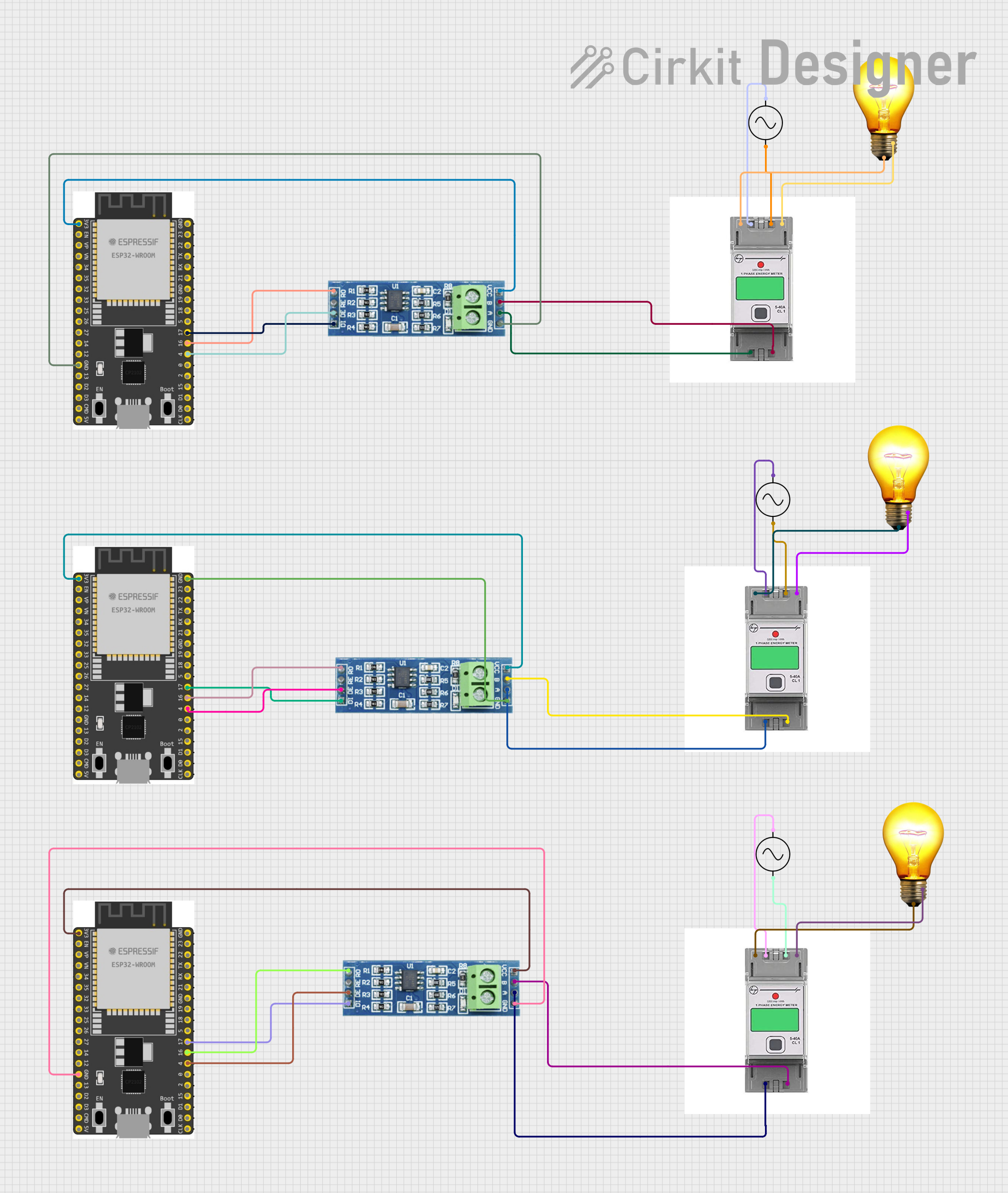
Arduino UNO Integration (Monitoring Example)
While the ATS itself does not directly interface with an Arduino, you can use an Arduino UNO to monitor the status of the ATS. For example, you can read the status output terminals to determine the active power source.
// ATS Monitoring with Arduino UNO
// This code reads the status of the ATS and indicates the active power source
// using LEDs connected to digital pins 8 and 9.

const int primaryStatusPin = 2; // Pin connected to primary source status output
const int backupStatusPin = 3;  // Pin connected to backup source status output
const int primaryLEDPin = 8;    // LED for primary source status
const int backupLEDPin = 9;     // LED for backup source status

void setup() {
  pinMode(primaryStatusPin, INPUT); // Set primary status pin as input
  pinMode(backupStatusPin, INPUT);  // Set backup status pin as input
  pinMode(primaryLEDPin, OUTPUT);   // Set primary LED pin as output
  pinMode(backupLEDPin, OUTPUT);    // Set backup LED pin as output
}

void loop() {
  int primaryStatus = digitalRead(primaryStatusPin); // Read primary status
  int backupStatus = digitalRead(backupStatusPin);   // Read backup status

  // Update LEDs based on ATS status
  digitalWrite(primaryLEDPin, primaryStatus); // Turn on/off primary LED
  digitalWrite(backupLEDPin, backupStatus);  // Turn on/off backup LED

  delay(500); // Small delay for stability
}
Troubleshooting and FAQs
Common Issues and Solutions
ATS Does Not Switch to Backup Power:
- Cause: Backup power source is not available or improperly connected.
- Solution: Verify the backup source connection and ensure it is operational.
Frequent Switching Between Sources:
- Cause: Instability in the primary power source.
- Solution: Check the primary source for voltage fluctuations and resolve the issue.
Load Does Not Receive Power:
- Cause: Incorrect wiring or blown fuse.
- Solution: Double-check the wiring and replace any blown fuses.
Control Circuit Malfunction:
- Cause: Faulty control wiring or incorrect control voltage.
- Solution: Inspect the control wiring and ensure the correct voltage is supplied.
FAQs
Q: Can the ATS handle single-phase systems?
A: No, this ATS is specifically designed for three-phase systems. Use a single-phase ATS for single-phase applications.Q: How often should the ATS be maintained?
A: Perform routine inspections every 6 months and a full maintenance check annually.Q: Can the ATS be used outdoors?
A: Only if the enclosure has an appropriate IP rating (e.g., IP65) for outdoor use.Q: What happens if both power sources fail?
A: The ATS will not supply power to the load. Consider adding a UPS for critical systems.