
How to Use Step-Down Buck Converter: Examples, Pinouts, and Specs
 Design with Step-Down Buck Converter in Cirkit Designer
Introduction
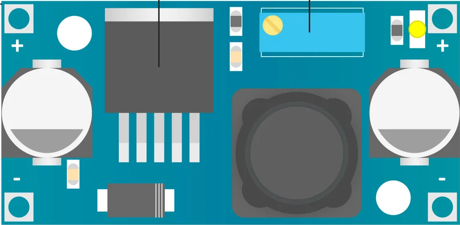
The LM2596 is a step-down (buck) DC-DC converter manufactured by Texas Instruments. It is designed to efficiently step down a higher input voltage to a lower output voltage, making it ideal for applications requiring regulated power supply. The LM2596 is widely used due to its high efficiency, ease of use, and ability to handle significant output current.
Explore Projects Built with Step-Down Buck Converter
 Open Project in Cirkit Designer
 Open Project in Cirkit Designer
 Open Project in Cirkit Designer
 Open Project in Cirkit Designer
Explore Projects Built with Step-Down Buck Converter
Open Project in Cirkit DesignerOpen Project in Cirkit DesignerOpen Project in Cirkit DesignerOpen Project in Cirkit DesignerCommon Applications and Use Cases
- Powering microcontrollers and embedded systems (e.g., Arduino, Raspberry Pi)
- Battery-powered devices
- Industrial automation systems
- LED drivers
- Consumer electronics requiring regulated DC voltage
Technical Specifications
The LM2596 is a versatile and robust component. Below are its key technical details:
| Parameter | Value |
|---|---|
| Input Voltage Range | 4.5V to 40V |
| Output Voltage Range | 1.23V to 37V (adjustable) |
| Output Current | Up to 3A |
| Efficiency | Up to 90% |
| Switching Frequency | 150 kHz |
| Operating Temperature Range | -40°C to +125°C |
| Package Type | TO-220, TO-263 |
Pin Configuration and Descriptions
The LM2596 is typically available in a 5-pin TO-220 or TO-263 package. Below is the pinout description:
| Pin Number | Pin Name | Description |
|---|---|---|
| 1 | VIN | Input voltage pin. Connect to the unregulated DC input voltage. |
| 2 | Output | Regulated DC output voltage. |
| 3 | Ground (GND) | Ground pin. Connect to the system ground. |
| 4 | Feedback | Feedback pin. Used to set the output voltage via an external resistor divider. |
| 5 | ON/OFF | Enable pin. Logic high enables the converter; logic low disables it. |
Usage Instructions
How to Use the LM2596 in a Circuit
- Input Voltage: Connect the input voltage (4.5V to 40V) to the VIN pin. Ensure the input voltage is higher than the desired output voltage.
- Output Voltage Adjustment: Use a resistor divider network connected to the Feedback pin to set the desired output voltage. The formula for output voltage is: [ V_{OUT} = V_{REF} \times \left(1 + \frac{R_2}{R_1}\right) ] where ( V_{REF} = 1.23V ), ( R_1 ) is the resistor connected between the Feedback pin and ground, and ( R_2 ) is the resistor connected between the Feedback pin and the output.
- Inductor and Capacitors: Select an appropriate inductor and input/output capacitors based on the desired output voltage and current. Refer to the datasheet for recommended values.
- Enable Pin: Connect the ON/OFF pin to logic high (or leave it floating) to enable the converter. Pull it to ground to disable the converter.
- Heat Dissipation: If operating at high currents, ensure proper heat dissipation using a heatsink or adequate PCB thermal design.
Example: Using LM2596 with Arduino UNO
The LM2596 can be used to power an Arduino UNO from a 12V source by stepping down the voltage to 5V. Below is an example circuit and Arduino code:
Circuit Connections
- Connect the 12V input to the VIN pin of the LM2596.
- Set the output voltage to 5V using a resistor divider.
- Connect the 5V output to the Arduino UNO's 5V pin.
- Connect the GND pin of the LM2596 to the Arduino's GND.
Arduino Code Example
// Example code to blink an LED using Arduino UNO powered by LM2596
// Ensure the LM2596 output is set to 5V before connecting to Arduino

const int ledPin = 13; // Built-in LED pin on Arduino UNO

void setup() {
  pinMode(ledPin, OUTPUT); // Set LED pin as output
}

void loop() {
  digitalWrite(ledPin, HIGH); // Turn the LED on
  delay(1000);               // Wait for 1 second
  digitalWrite(ledPin, LOW);  // Turn the LED off
  delay(1000);               // Wait for 1 second
}
Important Considerations and Best Practices
- Input Voltage: Ensure the input voltage is at least 3V higher than the desired output voltage for proper regulation.
- Heat Management: Use a heatsink or proper PCB layout to dissipate heat, especially when operating at high currents.
- Component Selection: Use low ESR capacitors and an appropriately rated inductor for stable operation.
- Output Voltage Adjustment: Double-check the resistor divider values to ensure the correct output voltage.
Troubleshooting and FAQs
Common Issues and Solutions
No Output Voltage
- Check if the input voltage is within the specified range.
- Ensure the ON/OFF pin is set to logic high or left floating.
- Verify the resistor divider network for correct output voltage configuration.
Overheating
- Ensure proper heat dissipation using a heatsink or thermal vias on the PCB.
- Check if the load current exceeds the maximum rated 3A.
Output Voltage Instability
- Use low ESR capacitors for input and output filtering.
- Verify the inductor value and ensure it meets the recommended specifications.
Incorrect Output Voltage
- Double-check the resistor divider values and connections.
- Ensure the Feedback pin is properly connected.
FAQs
Q1: Can the LM2596 be used for battery charging?
A1: Yes, the LM2596 can be used for battery charging applications, but additional circuitry (e.g., current limiting) may be required for safe operation.
Q2: What is the maximum output current of the LM2596?
A2: The LM2596 can deliver up to 3A of output current, provided proper heat dissipation is ensured.
Q3: Can the LM2596 output voltage be adjusted dynamically?
A3: Yes, the output voltage can be adjusted dynamically by varying the resistor divider network connected to the Feedback pin.
Q4: Is the LM2596 suitable for powering sensitive electronics?
A4: Yes, the LM2596 provides a stable and regulated output, making it suitable for powering sensitive electronics like microcontrollers and sensors.
By following this documentation, users can effectively integrate the LM2596 step-down buck converter into their projects for efficient voltage regulation.