How to Use 7-Segment Display: Examples, Pinouts, and Specs
Introduction
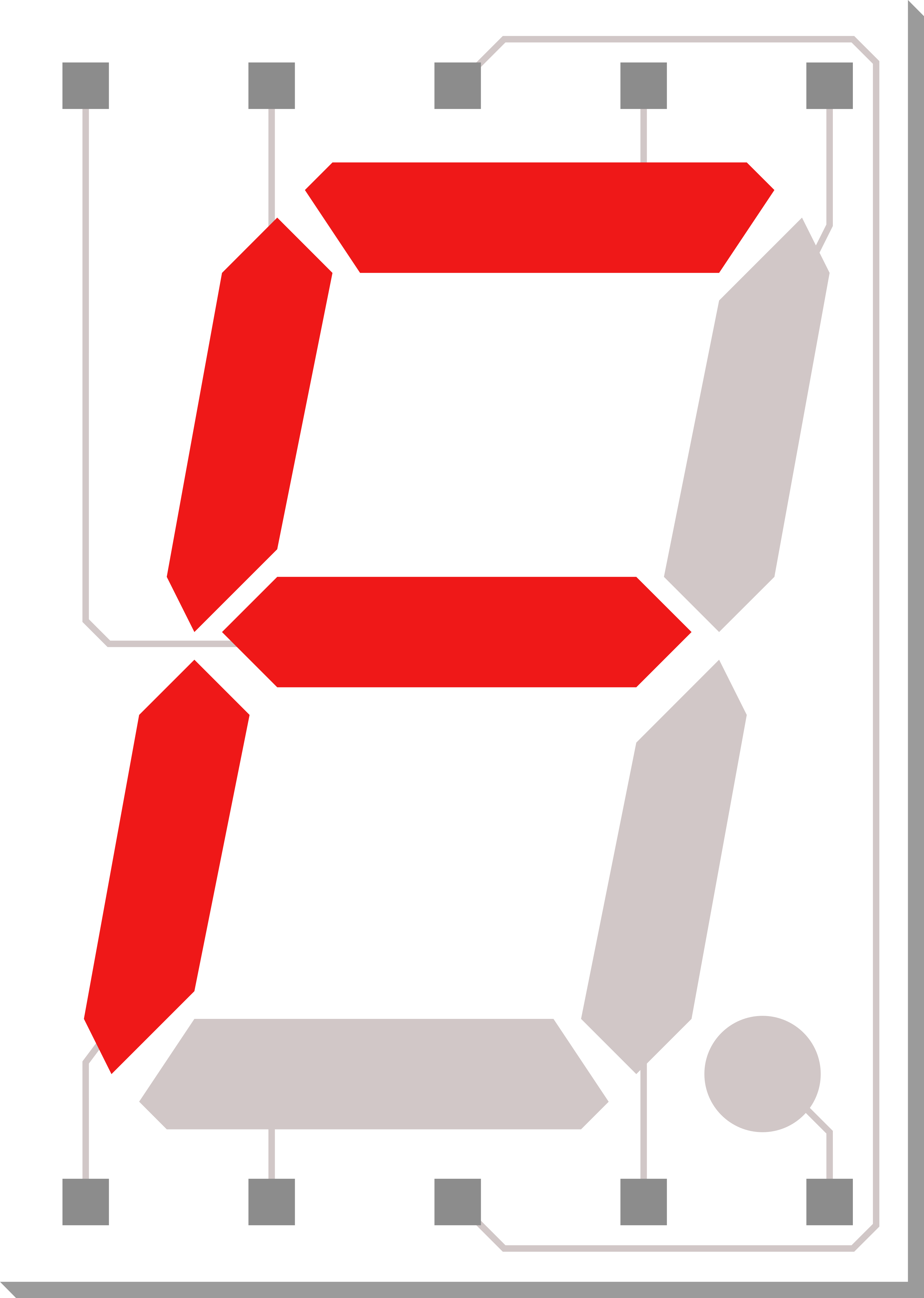
A 7-segment display is a form of electronic display device used to show decimal numerals and, in some cases, a limited number of alphabetical characters. It is a common, simple, and cost-effective solution for displaying numerical information. Each segment in the display is a small light-emitting diode (LED) or a liquid crystal display (LCD) that can be illuminated independently. These displays are widely used in digital clocks, electronic meters, basic calculators, and other devices that require numerical output.
Explore Projects Built with 7-Segment Display
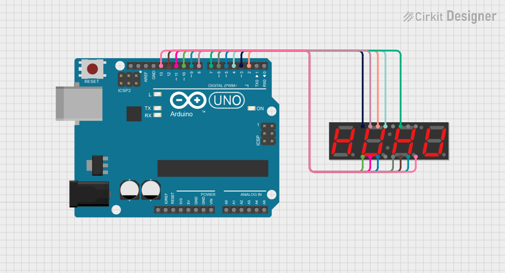
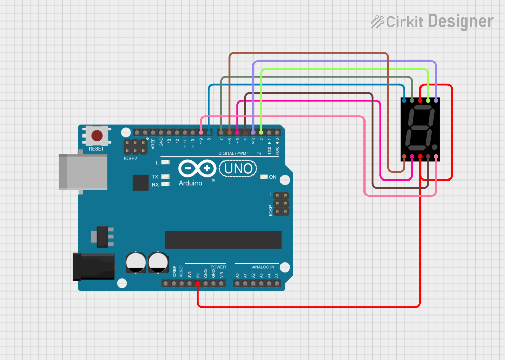
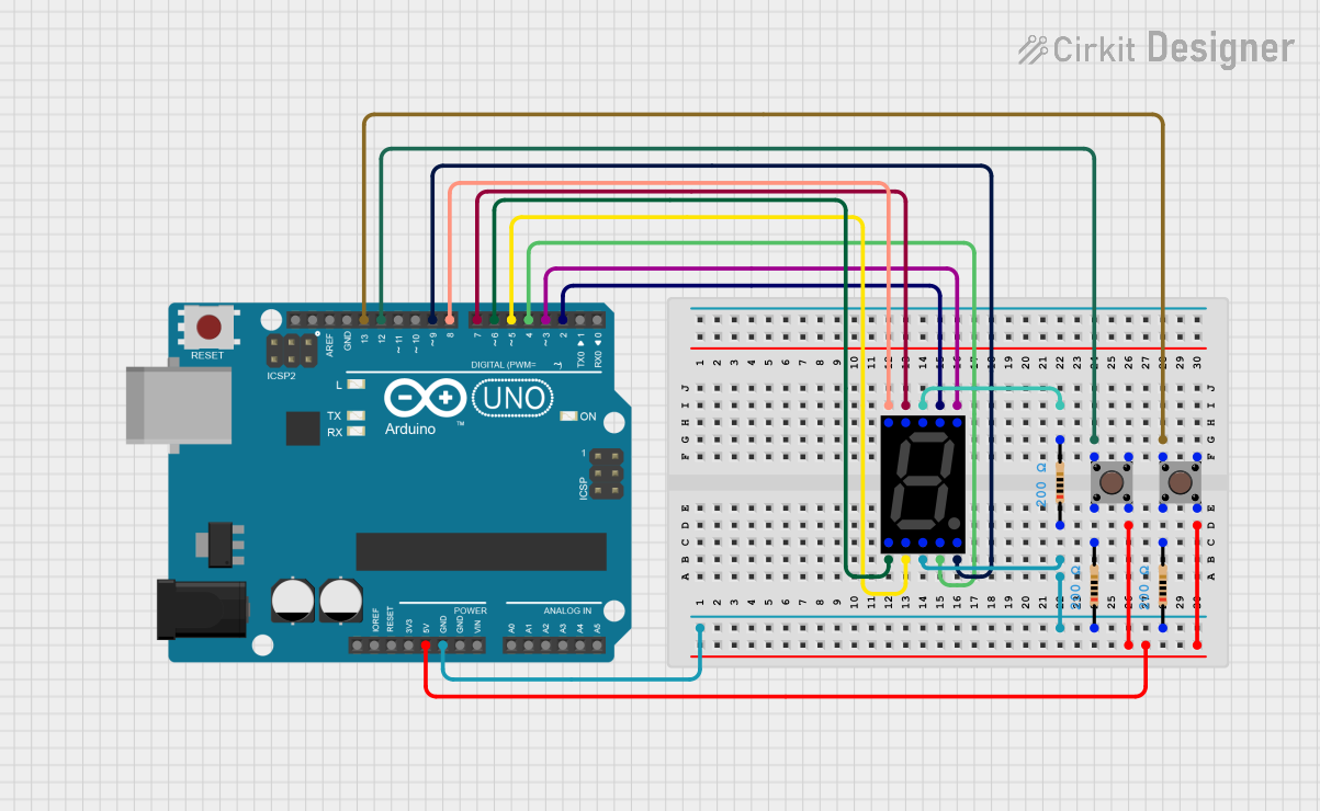
Explore Projects Built with 7-Segment Display
Technical Specifications
Key Technical Details
- Type: Common Cathode or Common Anode
- Forward Voltage (per segment): Typically 2.0V for red LEDs
- Forward Current (per segment): 10-20 mA is common
- Peak Wavelength: Depends on color (e.g., 660 nm for red)
- Luminous Intensity: Depends on the specific model and color
Pin Configuration and Descriptions
The pin configuration for a common 7-segment display is as follows:
| Pin Number | Common Cathode | Common Anode | Segment |
|---|---|---|---|
| 1 | e | e | Segment E |
| 2 | d | d | Segment D |
| 3 | Common Cathode | Common Anode | Ground or Vcc |
| 4 | c | c | Segment C |
| 5 | Decimal Point | Decimal Point | Decimal Point |
| 6 | b | b | Segment B |
| 7 | a | a | Segment A |
| 8 | Common Cathode | Common Anode | Ground or Vcc |
| 9 | f | f | Segment F |
| 10 | g | g | Segment G |
Segments are labeled from 'a' to 'g' plus the decimal point. The common pin is either connected to ground (common cathode) or Vcc (common anode), depending on the type of display.
Usage Instructions
How to Use in a Circuit
- Identify the Type: Determine if your 7-segment display is common cathode or common anode.
- Connect Common Pins: For common cathode displays, connect the common pins to ground. For common anode displays, connect them to Vcc.
- Resistors: Connect a current-limiting resistor (220-330 ohms) in series with each segment to prevent damage to the LEDs.
- Control Pins: Connect the other end of the resistors to the control pins (microcontroller or other driver IC pins).
- Driving the Display: To display a number, activate the corresponding segments by setting the control pins to HIGH for common cathode or LOW for common anode.
Best Practices
- Always use current-limiting resistors to prevent damage to the LEDs.
- Use multiplexing if you are controlling multiple displays to save on control pins.
- Consider using a dedicated driver IC to simplify the control of the display.
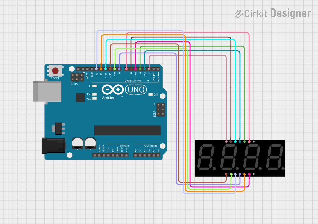
Example Code for Arduino UNO
This example demonstrates how to control a common cathode 7-segment display with an Arduino UNO.
// Define the LED segment and decimal point pins
int segments[] = {2, 3, 4, 5, 6, 7, 8, 9}; // Pins for segments a-g and decimal point

void setup() {
  // Set all the segment pins as output
  for (int i = 0; i < 8; i++) {
    pinMode(segments[i], OUTPUT);
  }
}

void loop() {
  // Display numbers 0-9 with a one-second delay
  for (int num = 0; num <= 9; num++) {
    displayNumber(num);
    delay(1000);
  }
}

// Function to display numbers on the 7-segment display
void displayNumber(int num) {
  // Array of byte values to represent numbers 0-9 on the display
  byte numbers[] = {
    0b00111111, // 0
    0b00000110, // 1
    0b01011011, // 2
    0b01001111, // 3
    0b01100110, // 4
    0b01101101, // 5
    0b01111101, // 6
    0b00000111, // 7
    0b01111111, // 8
    0b01101111  // 9
  };

  // Write the correct pattern to the segments
  for (int segment = 0; segment < 7; segment++) {
    // Use bitwise AND to determine if the segment should be lit
    bool isLit = numbers[num] & (1 << segment);
    digitalWrite(segments[segment], isLit ? HIGH : LOW);
  }
}
Troubleshooting and FAQs
Common Issues
- Segments not lighting up: Check the connections and ensure that the common pins are correctly connected to either ground or Vcc.
- Dim segments: Ensure that the current-limiting resistors are of the correct value and that the power supply is adequate.
- Incorrect numbers displayed: Verify that the segment control pins are connected to the correct Arduino pins and that the code matches the pin configuration.
Solutions and Tips
- Double-check wiring against the pin configuration table.
- Use a multimeter to verify that each segment receives the correct voltage.
- If using multiple displays, consider using a shift register or multiplexing to manage pin usage efficiently.
FAQs
Q: Can I use a 7-segment display without a microcontroller? A: Yes, you can use a combination of switches or a dedicated decoder IC to control a 7-segment display without a microcontroller.
Q: How can I display letters on a 7-segment display? A: Some letters can be approximated using the segments (e.g., 'A', 'b', 'C', 'd', 'E', 'F'), but not all letters can be displayed due to the limited number of segments.
Q: Can I chain multiple 7-segment displays together? A: Yes, you can chain multiple displays together, but you will need to use multiplexing or a driver IC to control them effectively.