How to Use MOS FET Trigger Drive Switch - flipped: Examples, Pinouts, and Specs
Introduction
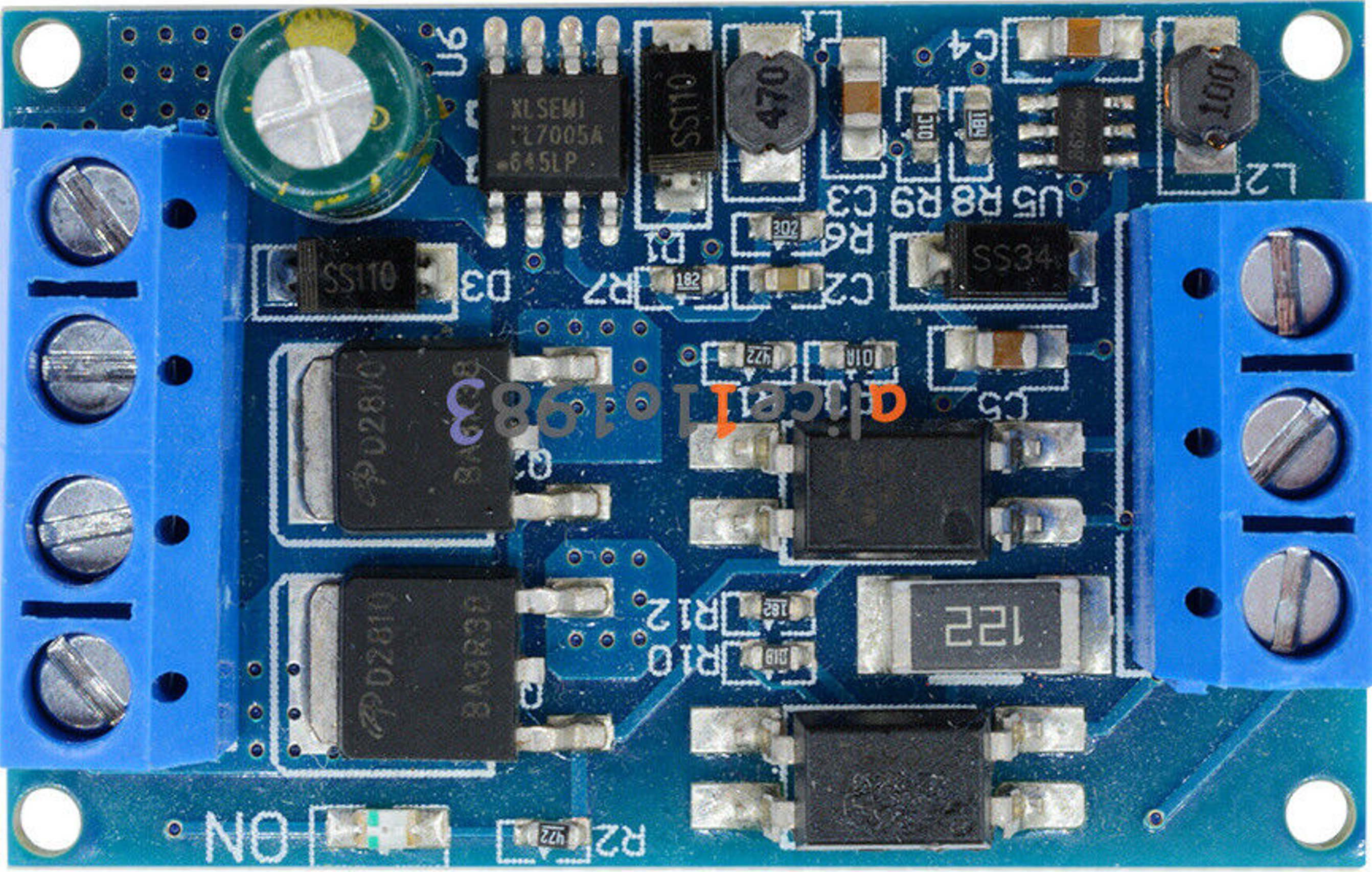
The MOSFET Trigger Drive Switch, manufactured by OWN with part ID 2, is a versatile electronic component designed to control the flow of current in a circuit. This Metal-Oxide-Semiconductor Field-Effect Transistor (MOSFET) is used primarily as a switch, and the 'flipped' designation indicates a specific configuration or orientation for the component.
Explore Projects Built with MOS FET Trigger Drive Switch - flipped


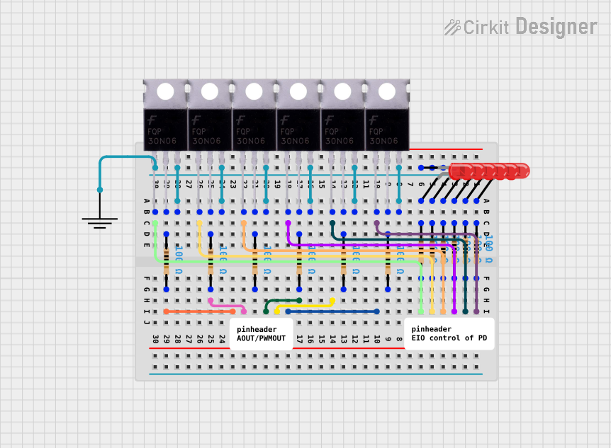
Explore Projects Built with MOS FET Trigger Drive Switch - flipped
Common Applications and Use Cases
- Power Management: Efficiently switching power to various parts of a circuit.
- Motor Control: Driving motors in robotics and automation systems.
- LED Control: Dimming and switching LEDs in lighting applications.
- Signal Amplification: Amplifying weak signals in communication devices.
- Arduino Projects: Commonly used in DIY electronics projects involving microcontrollers like Arduino.
Technical Specifications
Key Technical Details
| Parameter | Value |
|---|---|
| Manufacturer | OWN |
| Part ID | 2 |
| Type | N-Channel MOSFET |
| Maximum Voltage | 60V |
| Maximum Current | 30A |
| Gate Threshold Voltage | 2-4V |
| R_DS(on) | 0.035Ω |
| Power Dissipation | 50W |
| Package Type | TO-220 |
Pin Configuration and Descriptions
| Pin Number | Pin Name | Description |
|---|---|---|
| 1 | Gate | Controls the MOSFET switching |
| 2 | Drain | Current flows from drain to source |
| 3 | Source | Current flows to the source |
| 4 | Substrate | Connected to the source internally |
Usage Instructions
How to Use the Component in a Circuit
- Identify the Pins: Ensure you correctly identify the Gate, Drain, and Source pins.
- Connect the Gate: Connect the Gate pin to the control signal, typically from a microcontroller like an Arduino.
- Connect the Drain: Connect the Drain pin to the load you wish to control (e.g., a motor or LED).
- Connect the Source: Connect the Source pin to the ground of the power supply.
- Power Supply: Ensure the power supply voltage does not exceed the maximum voltage rating of the MOSFET.
Important Considerations and Best Practices
- Heat Dissipation: Use a heat sink if the MOSFET is expected to dissipate significant power.
- Gate Resistor: Use a resistor (typically 10-100Ω) between the microcontroller and the Gate to limit the inrush current.
- Flyback Diode: When driving inductive loads like motors, use a flyback diode across the load to protect the MOSFET from voltage spikes.
Example Circuit with Arduino UNO
// Example code to control a MOSFET with an Arduino UNO
const int gatePin = 9; // Pin connected to the Gate of the MOSFET

void setup() {
  pinMode(gatePin, OUTPUT); // Set the gate pin as an output
}

void loop() {
  digitalWrite(gatePin, HIGH); // Turn on the MOSFET
  delay(1000); // Wait for 1 second
  digitalWrite(gatePin, LOW); // Turn off the MOSFET
  delay(1000); // Wait for 1 second
}
Troubleshooting and FAQs
Common Issues Users Might Face
MOSFET Not Switching:
- Solution: Ensure the Gate voltage is within the specified threshold (2-4V).
- Tip: Check the connections and ensure the control signal is correctly applied.
Overheating:
- Solution: Use a heat sink to dissipate excess heat.
- Tip: Ensure the MOSFET is not exceeding its maximum current rating.
Load Not Responding:
- Solution: Verify the load connections and ensure the load is functional.
- Tip: Check for any loose connections or broken wires.
FAQs
Q: Can I use this MOSFET with a 3.3V microcontroller?
- A: Yes, as long as the Gate threshold voltage is met, the MOSFET can be controlled by a 3.3V signal.
Q: Do I need a special driver for the MOSFET?
- A: For most applications, a direct connection to a microcontroller pin is sufficient. However, for high-speed switching, a dedicated MOSFET driver may be beneficial.
Q: What is the 'flipped' designation?
- A: The 'flipped' designation indicates a specific orientation or configuration of the MOSFET, which may affect how it is mounted or connected in a circuit.
This documentation provides a comprehensive guide to using the MOSFET Trigger Drive Switch - Flipped, ensuring both beginners and experienced users can effectively integrate this component into their projects.