How to Use ULN2803A: Examples, Pinouts, and Specs
Introduction
The ULN2803A is a high-voltage, high-current Darlington transistor array designed to simplify the interface between low-power digital circuits and high-power loads. It consists of eight NPN Darlington pairs, each capable of driving loads up to 500mA and withstanding voltages up to 50V. The component is equipped with built-in freewheeling diodes to protect against voltage spikes, making it ideal for inductive loads such as relays, solenoids, and motors.
Explore Projects Built with ULN2803A
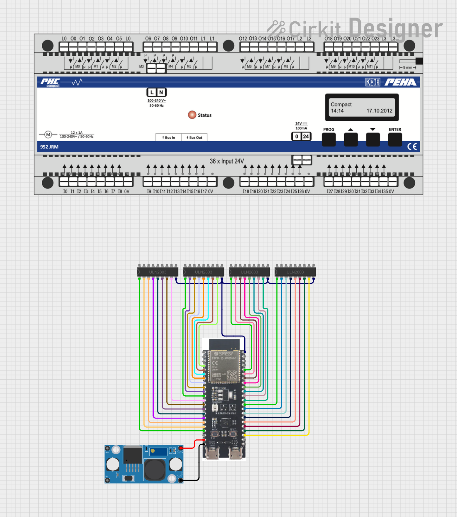
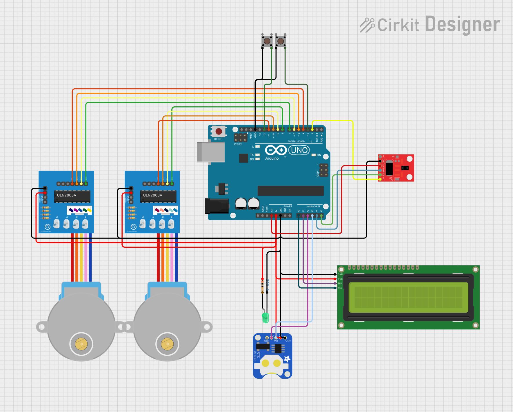
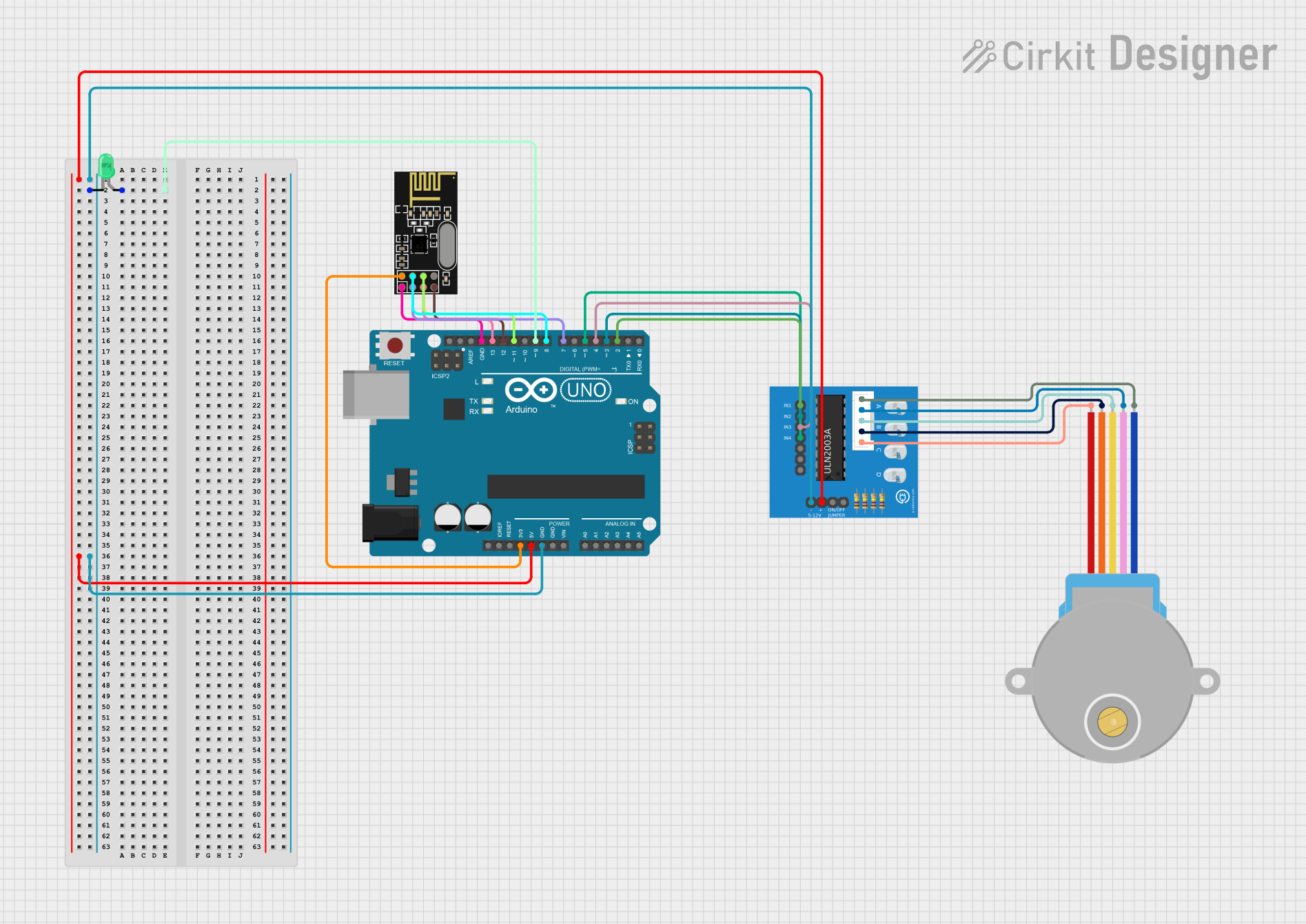
Explore Projects Built with ULN2803A
Common Applications and Use Cases
- Driving relays, solenoids, and stepper motors
- LED matrix and display control
- Interfacing microcontrollers with high-power devices
- Industrial automation and robotics
- Home appliances and automotive systems
Technical Specifications
The ULN2803A is a versatile component with the following key specifications:
| Parameter | Value |
|---|---|
| Supply Voltage (Vce) | Up to 50V |
| Output Current (Ic) | Up to 500mA per channel |
| Input Voltage (Vi) | 5V to 12V (TTL/CMOS compatible) |
| Number of Channels | 8 |
| Input Current (Ii) | 0.93mA (typical at 5V input) |
| Output Clamp Diode Voltage | 50V |
| Power Dissipation (Pd) | 2.25W (at 25°C ambient) |
| Package Type | DIP-18, SOIC-18 |
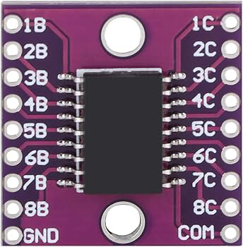
Pin Configuration and Descriptions
The ULN2803A is available in an 18-pin package. The pinout is as follows:
| Pin Number | Name | Description |
|---|---|---|
| 1-8 | Input 1-8 | Input pins for channels 1 to 8. Connect to the control signals from a microcontroller. |
| 9 | COM | Common cathode for freewheeling diodes. Connect to the positive supply of the load. |
| 10-17 | Output 8-1 | Output pins for channels 8 to 1. Connect to the load terminals. |
| 18 | GND | Ground pin. Connect to the ground of the circuit. |
Usage Instructions
How to Use the ULN2803A in a Circuit
- Connect the Inputs: Connect the input pins (1-8) to the control signals from a microcontroller or other digital logic device. Ensure the input voltage is within the specified range (5V to 12V).
- Connect the Outputs: Connect the output pins (10-17) to the load terminals. Each output pin corresponds to its respective input pin.
- Freewheeling Diodes: Connect the COM pin (pin 9) to the positive supply voltage of the load. This ensures the built-in diodes protect against voltage spikes from inductive loads.
- Ground Connection: Connect the GND pin (pin 18) to the ground of the circuit.
- Power the Circuit: Ensure the load voltage and current do not exceed the maximum ratings of the ULN2803A.
Important Considerations and Best Practices
- Current Limitation: Do not exceed 500mA per channel or the total power dissipation limit of the IC.
- Heat Management: If driving multiple high-current loads, consider adding a heatsink or improving ventilation to prevent overheating.
- Inductive Loads: Always connect the COM pin to the load's positive supply to utilize the internal freewheeling diodes.
- Input Voltage: Ensure the input voltage is compatible with the control signals from your microcontroller (e.g., 5V for Arduino).
Example: Using ULN2803A with Arduino UNO
The following example demonstrates how to use the ULN2803A to control a 12V relay with an Arduino UNO.
Circuit Connections
- Connect Arduino digital pin 2 to ULN2803A input pin 1.
- Connect ULN2803A output pin 10 to one terminal of the relay coil.
- Connect the other terminal of the relay coil to a 12V power supply.
- Connect the COM pin (pin 9) to the 12V power supply.
- Connect the GND pin (pin 18) to the Arduino GND.
Arduino Code
// Example code to control a relay using ULN2803A and Arduino UNO

#define RELAY_PIN 2  // Arduino pin connected to ULN2803A input pin 1

void setup() {
  pinMode(RELAY_PIN, OUTPUT); // Set the relay control pin as output
}

void loop() {
  digitalWrite(RELAY_PIN, HIGH); // Turn the relay ON
  delay(1000);                   // Wait for 1 second
  digitalWrite(RELAY_PIN, LOW);  // Turn the relay OFF
  delay(1000);                   // Wait for 1 second
}
Troubleshooting and FAQs
Common Issues and Solutions
Relay or Load Not Activating
- Cause: Insufficient input voltage or current.
- Solution: Ensure the input voltage is within the specified range (5V to 12V). Verify the microcontroller's output current is sufficient to drive the ULN2803A inputs.
Overheating
- Cause: Exceeding the maximum current or power dissipation limits.
- Solution: Reduce the load current or use fewer active channels simultaneously. Improve heat dissipation with a heatsink or better ventilation.
Voltage Spikes Damaging the Circuit
- Cause: Inductive loads generating back EMF.
- Solution: Ensure the COM pin is connected to the load's positive supply to utilize the internal freewheeling diodes.
Incorrect Output Behavior
- Cause: Miswiring or incorrect input signals.
- Solution: Double-check all connections and ensure the input signals are correctly configured.
FAQs
Q1: Can the ULN2803A drive LEDs directly?
A1: Yes, the ULN2803A can drive LEDs directly. However, you must use appropriate current-limiting resistors to prevent overdriving the LEDs.
Q2: Can I use the ULN2803A with a 3.3V microcontroller?
A2: The ULN2803A is designed for 5V to 12V input signals. If using a 3.3V microcontroller, consider using a level shifter or a different driver IC compatible with 3.3V logic.
Q3: What is the maximum total current the ULN2803A can handle?
A3: While each channel can handle up to 500mA, the total current should not exceed the power dissipation limit of 2.25W. Distribute the load evenly across channels to avoid overheating.