How to Use PD4-C5918L4204-E-08: Examples, Pinouts, and Specs
Introduction
The PD4-C5918L4204-E-08 is a high-performance photodetector manufactured by Nanotec. This component is designed to convert light into an electrical signal with exceptional sensitivity and fast response times. Its compact design and reliable performance make it ideal for a wide range of applications, including optical communication systems, light-based sensing, and imaging technologies.
Explore Projects Built with PD4-C5918L4204-E-08


Explore Projects Built with PD4-C5918L4204-E-08
Common Applications and Use Cases
- Optical Communication Systems: Used for detecting light signals in fiber-optic networks.
- Sensing Applications: Ideal for light intensity measurement and environmental monitoring.
- Imaging Systems: Suitable for high-speed imaging and light detection in cameras or scanners.
- Industrial Automation: Used in systems requiring precise light detection for control and monitoring.
Technical Specifications
Key Technical Details
| Parameter | Value |
|---|---|
| Wavelength Sensitivity | 400 nm to 1100 nm |
| Peak Sensitivity Wavelength | 850 nm |
| Response Time | < 10 ns |
| Reverse Voltage (Max) | 30 V |
| Dark Current | < 1 nA |
| Operating Temperature | -40°C to +85°C |
| Package Type | TO-46 |
Pin Configuration and Descriptions
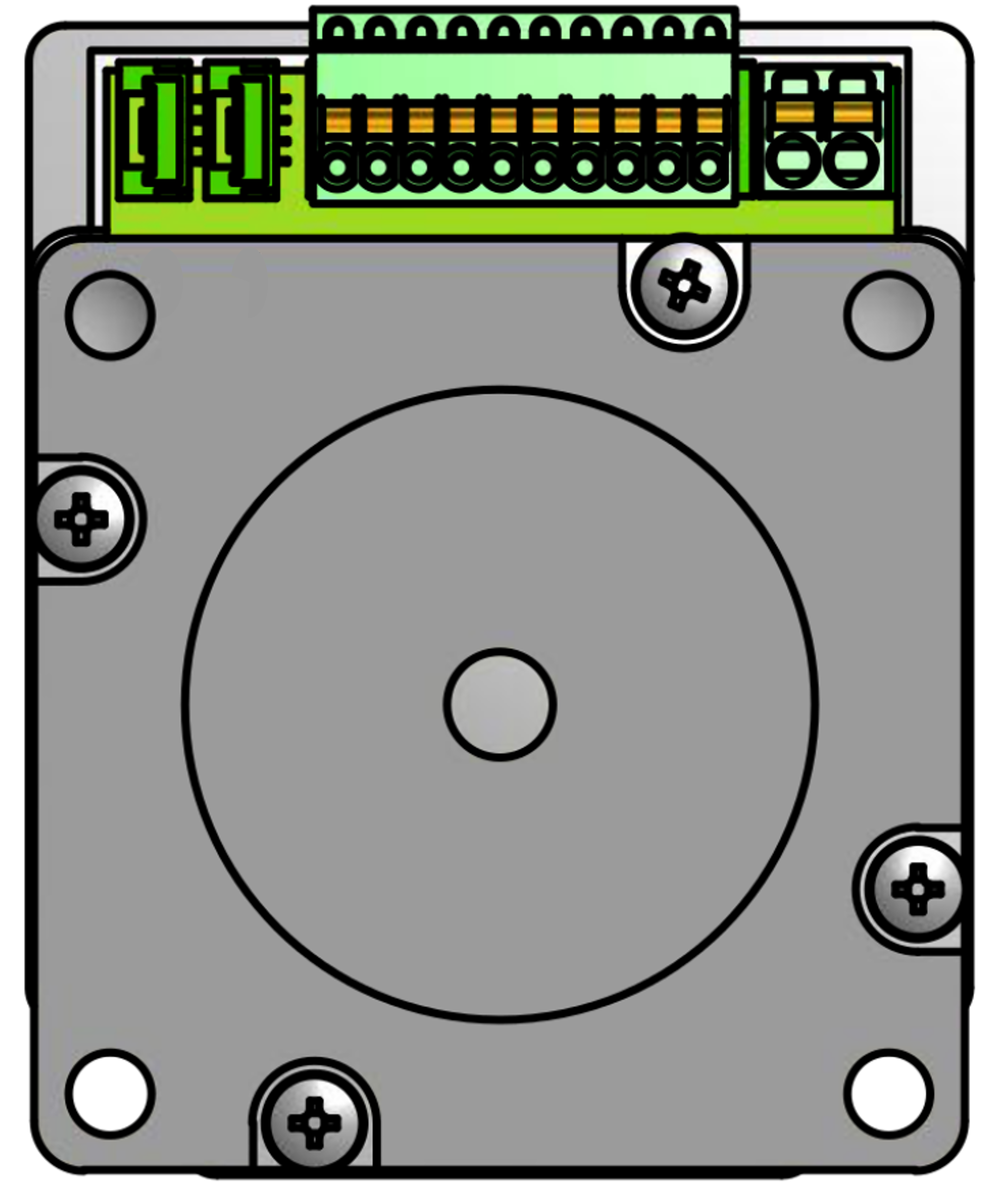
The PD4-C5918L4204-E-08 photodetector typically comes in a TO-46 package with three pins. Below is the pin configuration:
| Pin Number | Pin Name | Description |
|---|---|---|
| 1 | Anode | Positive terminal for the photodetector. |
| 2 | Cathode | Negative terminal for the photodetector. |
| 3 | Case Ground | Ground connection for the metal case (optional). |
Usage Instructions
How to Use the Component in a Circuit
- Power Supply: Ensure the photodetector is connected to a stable power source. The reverse voltage should not exceed 30 V to avoid damage.
- Circuit Design: Connect the anode to the positive terminal of the circuit and the cathode to the negative terminal. Use a resistor in series with the photodetector to limit current.
- Signal Processing: The output signal from the photodetector can be fed into an amplifier or microcontroller for further processing.
- Light Source: Ensure the photodetector is exposed to a light source within its sensitivity range (400 nm to 1100 nm) for optimal performance.
Important Considerations and Best Practices
- Avoid Overvoltage: Exceeding the maximum reverse voltage of 30 V can permanently damage the component.
- Minimize Noise: Use proper shielding and grounding techniques to reduce electrical noise in the circuit.
- Temperature Management: Operate the photodetector within the specified temperature range (-40°C to +85°C) to ensure reliability.
- Light Alignment: Align the photodetector with the light source for maximum sensitivity and accuracy.
Example: Connecting to an Arduino UNO
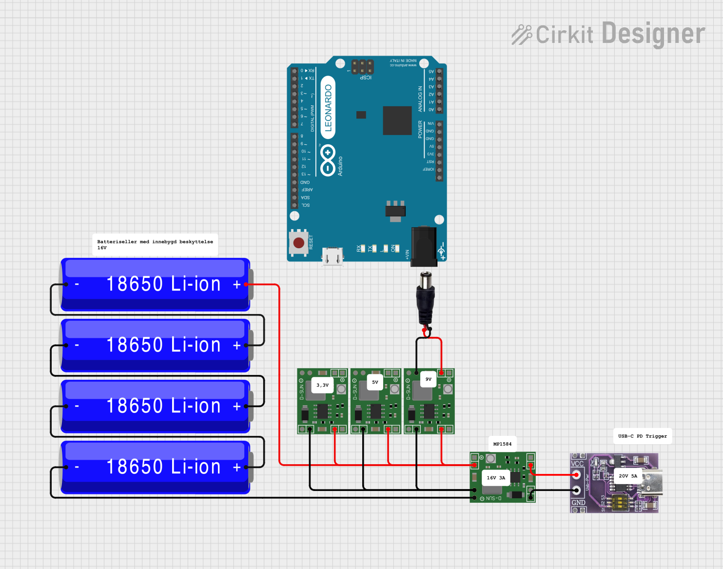
The PD4-C5918L4204-E-08 can be interfaced with an Arduino UNO for light intensity measurement. Below is an example circuit and code:
Circuit Diagram
- Connect the anode to a 5V power supply.
- Connect the cathode to an analog input pin (e.g., A0) on the Arduino through a 10 kΩ resistor.
- Connect the case ground to the Arduino's GND pin.
Arduino Code
// Example code for interfacing the PD4-C5918L4204-E-08 with Arduino UNO
// This code reads the photodetector's output and prints the light intensity.

const int photoPin = A0; // Analog pin connected to the photodetector's cathode

void setup() {
  Serial.begin(9600); // Initialize serial communication at 9600 baud
  pinMode(photoPin, INPUT); // Set the photodetector pin as input
}

void loop() {
  int lightValue = analogRead(photoPin); // Read the analog value from the photodetector
  Serial.print("Light Intensity: ");
  Serial.println(lightValue); // Print the light intensity value to the Serial Monitor
  delay(500); // Wait for 500 ms before the next reading
}
Troubleshooting and FAQs
Common Issues and Solutions
| Issue | Possible Cause | Solution |
|---|---|---|
| No output signal | Incorrect wiring or no light source | Verify connections and ensure proper alignment with the light source. |
| High noise in the output | Electrical interference or poor grounding | Use proper shielding and ensure a solid ground connection. |
| Component overheating | Exceeding the maximum reverse voltage | Check the power supply and ensure voltage is within the specified range. |
| Low sensitivity | Light source outside sensitivity range | Use a light source with a wavelength between 400 nm and 1100 nm. |
FAQs
Can the photodetector be used in outdoor environments?
- Yes, as long as the operating temperature is within -40°C to +85°C and the component is protected from moisture and dust.
What is the typical application for the case ground pin?
- The case ground is used to reduce noise and improve shielding in sensitive applications.
How can I increase the response speed of the photodetector?
- Minimize the capacitance in the circuit and use a high-speed amplifier for signal processing.
Is the photodetector compatible with other microcontrollers?
- Yes, it can be used with any microcontroller that has an analog input pin.
This documentation provides a comprehensive guide to understanding, using, and troubleshooting the PD4-C5918L4204-E-08 photodetector. For further assistance, refer to the manufacturer's datasheet or contact Nanotec support.