Cirkit Designer Logo
Cirkit Designer
Your all-in-one circuit design IDE
Home / 
Component Documentation

How to Use MQ-131 SENSOR OZONE GAS: Examples, Pinouts, and Specs

Image of MQ-131 SENSOR OZONE GAS
Cirkit Designer LogoDesign with MQ-131 SENSOR OZONE GAS in Cirkit Designer

Introduction

The MQ-131 Sensor is an electronic device specifically designed to detect the presence of ozone (O3) gas in the air. Ozone is a strong oxidizing agent and is used for disinfecting water, purifying air, and bleaching substances. Monitoring ozone levels is crucial in various industrial and environmental applications to ensure safety and compliance with health standards. Common applications of the MQ-131 sensor include air quality monitoring systems, environmental monitoring stations, and ozone generators for water treatment.

Explore Projects Built with MQ-131 SENSOR OZONE GAS

Use Cirkit Designer to design, explore, and prototype these projects online. Some projects support real-time simulation. Click "Open Project" to start designing instantly!
Arduino UNO Based Multi-Gas Detector
Image of AIRMS: A project utilizing MQ-131 SENSOR OZONE GAS in a practical application
This circuit is designed for environmental monitoring, featuring an Arduino UNO microcontroller interfaced with three different gas sensors: MQ-7 for carbon monoxide (CO) detection, MQ131 for ozone (O3) measurement, and MQ-135 for general air quality assessment. The sensors are powered by the Arduino's 5V output and their analog signals are read through the Arduino's analog input pins A0, A1, and A2 respectively. The embedded code reads the analog values from the sensors and outputs the readings via the serial interface, allowing for real-time monitoring of the gases.
Cirkit Designer LogoOpen Project in Cirkit Designer
Arduino-Based Air Quality Monitoring System with MQ Sensors
Image of AIRMS: A project utilizing MQ-131 SENSOR OZONE GAS in a practical application
This circuit is an air quality monitoring system using an Arduino UNO microcontroller connected to three different gas sensors: MQ-7 for carbon monoxide, MQ131 for ozone, and MQ-135 for general air quality. The Arduino reads analog signals from these sensors and outputs the readings via the serial interface for monitoring purposes.
Cirkit Designer LogoOpen Project in Cirkit Designer
Arduino UNO and LORA-Based Air Quality Monitoring System with Multiple Sensors
Image of sink: A project utilizing MQ-131 SENSOR OZONE GAS in a practical application
This circuit is an environmental monitoring system that uses an Arduino UNO to collect data from various sensors, including an MQ-7 gas sensor, an MQ131 ozone sensor, and a GP2Y1010AU0F dust sensor. The collected data is then transmitted wirelessly using a LORA module.
Cirkit Designer LogoOpen Project in Cirkit Designer
Arduino-Based Air Quality Monitoring System with Multiple Gas Sensors and GSM Module
Image of AIRMS: A project utilizing MQ-131 SENSOR OZONE GAS in a practical application
This circuit is an air quality monitoring system that uses an Arduino UNO to read data from various sensors, including the MQ-7 for CO detection, MQ131 for ozone detection, MQ-135 for general air quality, and a DHT11 for temperature and humidity. The Arduino processes the sensor data and can communicate the results via a SIM800L module for remote monitoring.
Cirkit Designer LogoOpen Project in Cirkit Designer

Explore Projects Built with MQ-131 SENSOR OZONE GAS

Use Cirkit Designer to design, explore, and prototype these projects online. Some projects support real-time simulation. Click "Open Project" to start designing instantly!
Image of AIRMS: A project utilizing MQ-131 SENSOR OZONE GAS in a practical application
Arduino UNO Based Multi-Gas Detector
This circuit is designed for environmental monitoring, featuring an Arduino UNO microcontroller interfaced with three different gas sensors: MQ-7 for carbon monoxide (CO) detection, MQ131 for ozone (O3) measurement, and MQ-135 for general air quality assessment. The sensors are powered by the Arduino's 5V output and their analog signals are read through the Arduino's analog input pins A0, A1, and A2 respectively. The embedded code reads the analog values from the sensors and outputs the readings via the serial interface, allowing for real-time monitoring of the gases.
Cirkit Designer LogoOpen Project in Cirkit Designer
Image of AIRMS: A project utilizing MQ-131 SENSOR OZONE GAS in a practical application
Arduino-Based Air Quality Monitoring System with MQ Sensors
This circuit is an air quality monitoring system using an Arduino UNO microcontroller connected to three different gas sensors: MQ-7 for carbon monoxide, MQ131 for ozone, and MQ-135 for general air quality. The Arduino reads analog signals from these sensors and outputs the readings via the serial interface for monitoring purposes.
Cirkit Designer LogoOpen Project in Cirkit Designer
Image of sink: A project utilizing MQ-131 SENSOR OZONE GAS in a practical application
Arduino UNO and LORA-Based Air Quality Monitoring System with Multiple Sensors
This circuit is an environmental monitoring system that uses an Arduino UNO to collect data from various sensors, including an MQ-7 gas sensor, an MQ131 ozone sensor, and a GP2Y1010AU0F dust sensor. The collected data is then transmitted wirelessly using a LORA module.
Cirkit Designer LogoOpen Project in Cirkit Designer
Image of AIRMS: A project utilizing MQ-131 SENSOR OZONE GAS in a practical application
Arduino-Based Air Quality Monitoring System with Multiple Gas Sensors and GSM Module
This circuit is an air quality monitoring system that uses an Arduino UNO to read data from various sensors, including the MQ-7 for CO detection, MQ131 for ozone detection, MQ-135 for general air quality, and a DHT11 for temperature and humidity. The Arduino processes the sensor data and can communicate the results via a SIM800L module for remote monitoring.
Cirkit Designer LogoOpen Project in Cirkit Designer

Technical Specifications

Key Technical Details

  • Target Gas: Ozone (O3)
  • Detection Range: 10 ppb to 2 ppm (parts per million)
  • Preheat Duration: 20 minutes (minimum)
  • Supply Voltage: Typically 5V
  • Heater Voltage: 5V±0.1V (AC or DC)
  • Load Resistance: Adjustable
  • Heater Resistance: 31Ω±3Ω (at room temperature)
  • Heater Power Consumption: Approx. 150mW

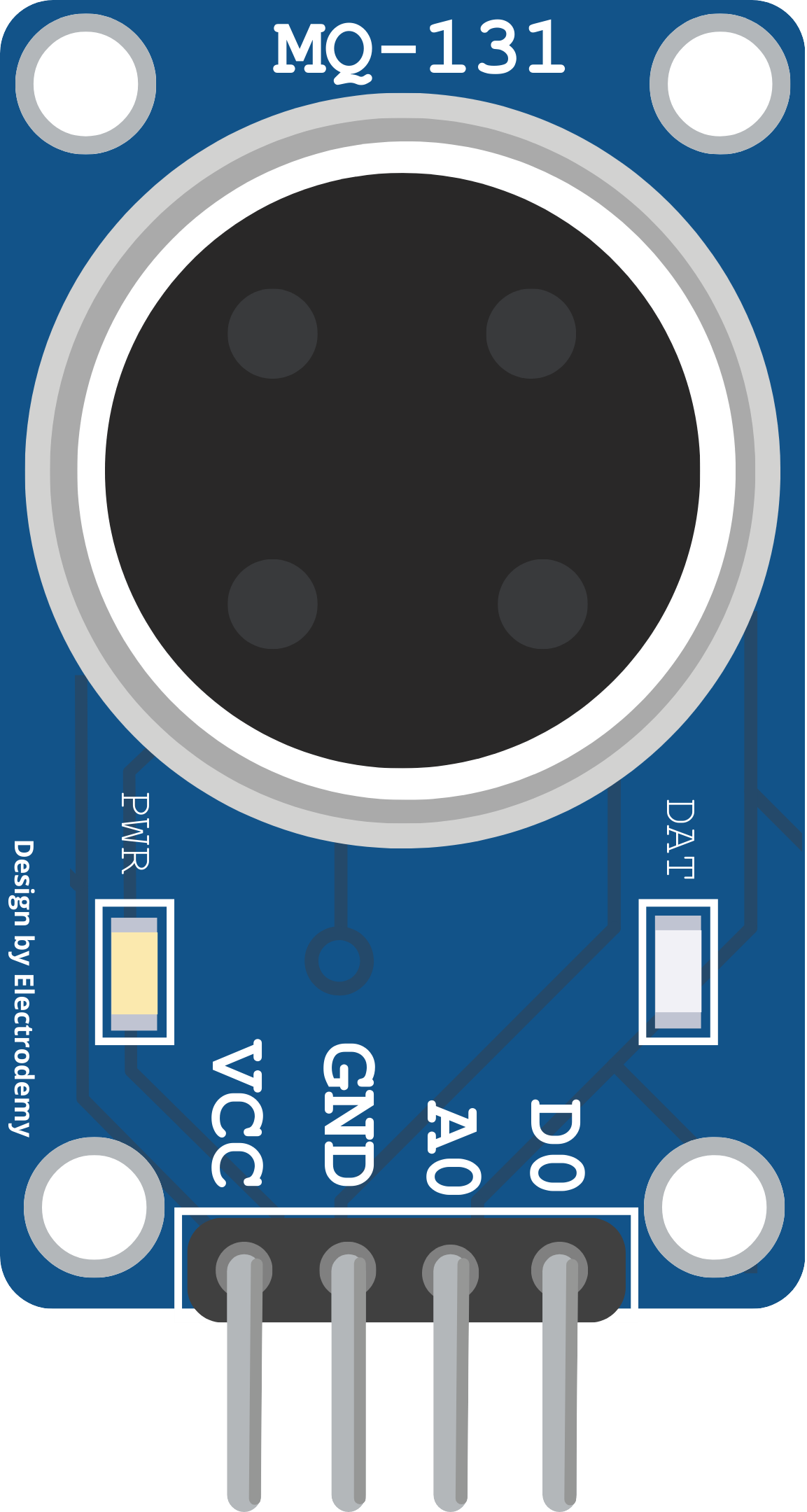
Pin Configuration and Descriptions

Pin Number Pin Name Description
1 VCC Power supply (5V)
2 GND Ground
3 DO Digital output (TTL logic level)
4 AO Analog output (proportional to O3)

Usage Instructions

Integration with a Circuit

To use the MQ-131 sensor in a circuit, follow these steps:

  1. Connect the VCC pin to a 5V power supply.
  2. Connect the GND pin to the ground of the power supply.
  3. The AO pin provides an analog voltage output that is proportional to the concentration of ozone. Connect this pin to an analog input on your microcontroller.
  4. The DO pin provides a digital output which switches high or low based on a threshold value. This can be connected to a digital input on your microcontroller.

Important Considerations and Best Practices

  • Calibration: The sensor requires calibration to accurately measure ozone concentrations. This involves exposing the sensor to a known concentration of ozone and adjusting the load resistance until the desired output is achieved.
  • Preheating: Before taking measurements, the sensor should be preheated for at least 20 minutes.
  • Environment: Avoid using the sensor in environments with high concentration of corrosive gases, as this can damage the sensor.
  • Temperature and Humidity: The sensor's performance can be affected by temperature and humidity. Ensure that measurements are taken within the recommended operating conditions.

Troubleshooting and FAQs

Common Issues

  • Inaccurate Readings: If the sensor provides inaccurate readings, recalibrate the sensor and ensure that it is operating within the recommended temperature and humidity range.
  • No Output: Check the power supply connections and ensure that the sensor is properly preheated.

Solutions and Tips

  • Calibration: Perform regular calibration to maintain accuracy.
  • Preheating: Always preheat the sensor before use.
  • Avoid Contaminants: Keep the sensor away from organic solvents and oils.

FAQs

Q: How often should the sensor be calibrated? A: The sensor should be calibrated periodically, depending on usage and environmental conditions.

Q: Can the sensor detect other gases? A: The MQ-131 is designed for ozone detection, but it may respond to other oxidizing gases.

Q: What is the lifespan of the sensor? A: The lifespan can vary based on usage, but typically MQ-131 sensors can last for several years with proper maintenance.

Example Arduino Code

// MQ-131 Ozone Gas Sensor Example Code for Arduino UNO
int analogPin = A0; // Connect AO pin of MQ-131 to A0 of Arduino
int readValue;      // Stores the value read from the sensor
float ozonePPM;     // Stores the calculated ozone PPM

void setup() {
  Serial.begin(9600); // Start serial communication at 9600 baud rate
}

void loop() {
  readValue = analogRead(analogPin); // Read the analog value from sensor
  ozonePPM = readValue * (3.3 / 1023.0); // Convert to ozone concentration
  Serial.print("Ozone concentration: ");
  Serial.print(ozonePPM);
  Serial.println(" ppm");
  delay(1000); // Wait for 1 second before the next read
}

Note: The above code provides a basic example of how to read the analog output from the MQ-131 sensor. The conversion from the analog reading to ozone concentration (PPM) requires calibration with a known ozone source. The formula used in the code is for illustrative purposes and should be adjusted based on calibration data.