How to Use 3s bms: Examples, Pinouts, and Specs
Introduction
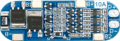
A 3S Battery Management System (BMS) is designed to monitor and manage the performance of a lithium-ion battery pack consisting of three cells connected in series. It ensures safe and efficient operation by balancing cell voltages, protecting against overcharging, over-discharging, and short circuits, and monitoring temperature. Additionally, some 3S BMS modules provide communication interfaces for integration with external devices.
Explore Projects Built with 3s bms


Explore Projects Built with 3s bms
Common Applications and Use Cases
- Lithium-ion battery packs for electric vehicles (EVs)
- Portable power banks and energy storage systems
- Solar energy storage solutions
- Uninterruptible Power Supplies (UPS)
- Robotics and drones
Technical Specifications
Below are the key technical details for a typical 3S BMS module. Note that specifications may vary depending on the manufacturer.
General Specifications
| Parameter | Value |
|---|---|
| Battery Configuration | 3 cells in series (3S) |
| Nominal Voltage | 11.1V (3.7V per cell) |
| Maximum Voltage | 12.6V (4.2V per cell) |
| Overcharge Protection | ~4.25V per cell |
| Over-discharge Protection | ~2.5V per cell |
| Maximum Continuous Current | 10A, 20A, or higher (varies) |
| Balancing Current | ~50mA to 100mA |
| Operating Temperature | -20°C to 60°C |
Pin Configuration and Descriptions
| Pin Name | Description |
|---|---|
| B+ | Positive terminal of the battery pack |
| B- | Negative terminal of the battery pack |
| P+ | Positive terminal of the load or charger |
| P- | Negative terminal of the load or charger |
| B1 | Connection to the positive terminal of the first cell in the series |
| B2 | Connection to the positive terminal of the second cell in the series |
| B3 | Connection to the positive terminal of the third cell in the series |
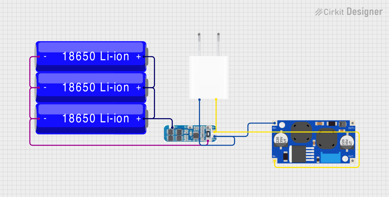
Usage Instructions
How to Use the 3S BMS in a Circuit
Connect the Battery Pack:
- Connect the B+ pin to the positive terminal of the battery pack.
- Connect the B- pin to the negative terminal of the battery pack.
- Connect B1, B2, and B3 to the positive terminals of the first, second, and third cells, respectively.
Connect the Load and Charger:
- Connect the P+ pin to the positive terminal of the load or charger.
- Connect the P- pin to the negative terminal of the load or charger.
Verify Connections:
- Double-check all connections to ensure proper polarity and avoid short circuits.
Power On:
- Once all connections are secure, the BMS will begin monitoring and managing the battery pack.
Important Considerations and Best Practices
- Cell Matching: Ensure that all cells in the battery pack have similar capacities and internal resistances to avoid imbalances.
- Heat Dissipation: Avoid placing the BMS in an enclosed space without proper ventilation, as it may generate heat during operation.
- Avoid Overloading: Do not exceed the maximum continuous current rating of the BMS.
- Use Proper Wiring: Use wires with appropriate gauge ratings to handle the current without overheating.
Example: Connecting a 3S BMS to an Arduino UNO
If your 3S BMS supports communication (e.g., via UART or I2C), you can interface it with an Arduino UNO to monitor battery parameters. Below is an example code snippet for reading data from a BMS with UART communication.
#include <SoftwareSerial.h>

// Define RX and TX pins for communication with the BMS
SoftwareSerial BMS(10, 11); // RX = Pin 10, TX = Pin 11

void setup() {
  Serial.begin(9600);       // Initialize Serial Monitor
  BMS.begin(9600);          // Initialize communication with the BMS
  Serial.println("3S BMS Monitoring Started");
}

void loop() {
  if (BMS.available()) {
    // Read data from the BMS
    String data = BMS.readString();
    Serial.println("BMS Data: " + data); // Print data to Serial Monitor
  }
  delay(500); // Wait for 500ms before the next read
}
Note: The exact communication protocol and data format depend on the specific BMS module. Refer to the manufacturer's datasheet for details.
Troubleshooting and FAQs
Common Issues and Solutions
Issue: The BMS is not balancing the cells.
- Solution: Ensure that the cells are properly connected to the B1, B2, and B3 pins. Verify that the cells have similar capacities and are not significantly imbalanced.
Issue: The BMS shuts down unexpectedly.
- Solution: Check if the load current exceeds the maximum continuous current rating. Also, verify that the battery pack voltage is within the operating range.
Issue: The BMS overheats during operation.
- Solution: Ensure proper ventilation and avoid placing the BMS in an enclosed space. Check for any short circuits or excessive current draw.
Issue: The Arduino is not receiving data from the BMS.
- Solution: Verify the RX and TX connections between the Arduino and the BMS. Ensure that the baud rate matches the BMS communication settings.
FAQs
Q: Can I use a 3S BMS with a 4S battery pack?
- A: No, a 3S BMS is specifically designed for 3-cell battery packs. Using it with a 4S pack may result in improper operation or damage.
Q: Does the BMS support charging and discharging simultaneously?
- A: Yes, most 3S BMS modules support simultaneous charging and discharging. However, ensure that the current ratings are not exceeded.
Q: How do I know if the BMS is balancing the cells?
- A: Some BMS modules have indicator LEDs or communication interfaces that provide balancing status. Alternatively, you can measure the cell voltages to confirm.
Q: Can I use the BMS with other battery chemistries?
- A: The 3S BMS is typically designed for lithium-ion or lithium-polymer batteries. Using it with other chemistries may require additional configuration or may not be supported.
This concludes the documentation for the 3S Battery Management System (BMS). Always refer to the manufacturer's datasheet for specific details and guidelines.