How to Use HX711: Examples, Pinouts, and Specs
Introduction
The HX711 is a precision 24-bit analog-to-digital converter (ADC) designed for applications requiring high accuracy and stability, such as weigh scales and industrial control systems. Manufactured by Soldered, the Soldered HX711 Breakout provides an easy-to-use interface for measuring small changes in voltage, making it ideal for load cells and other sensors.
Explore Projects Built with HX711
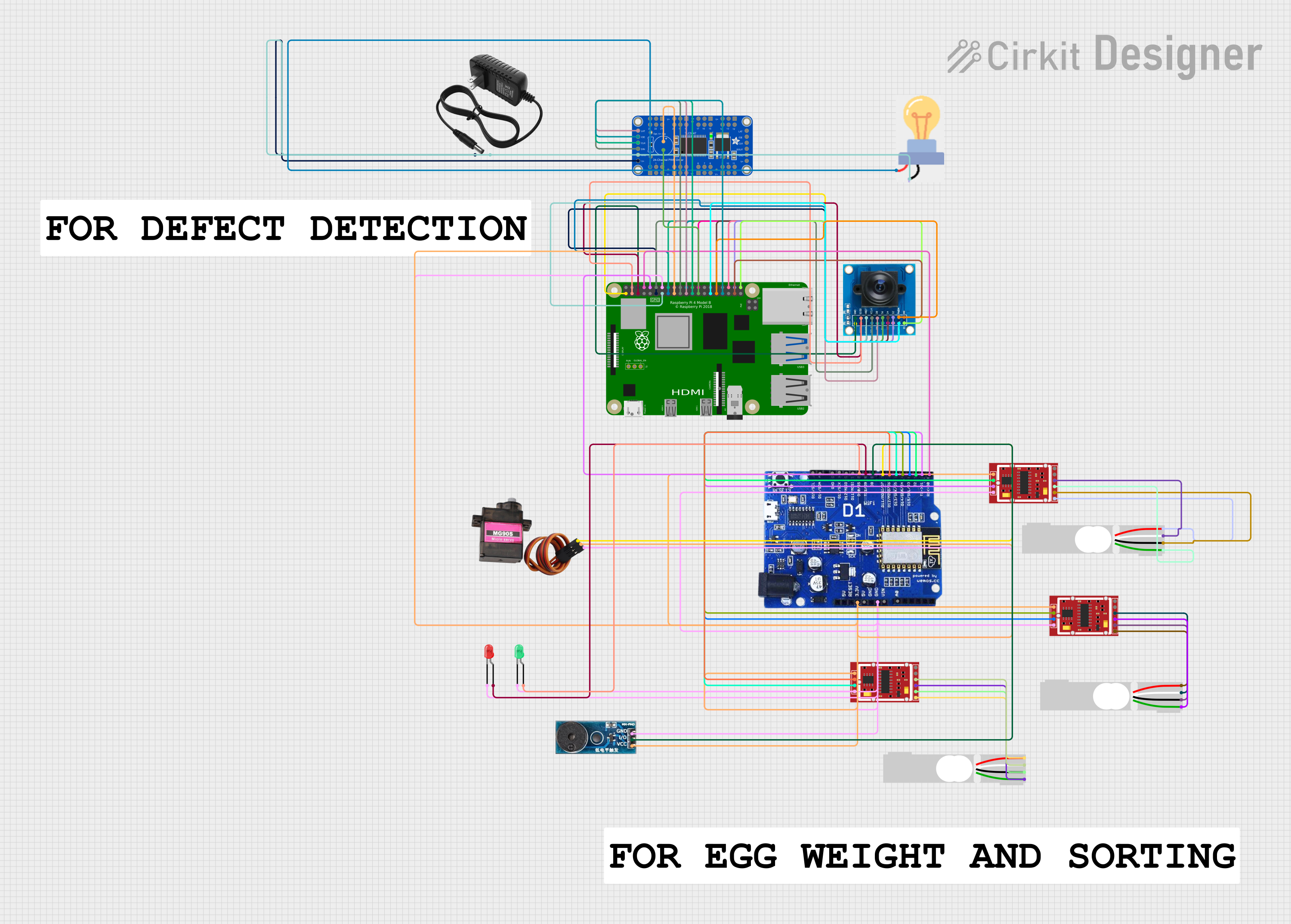
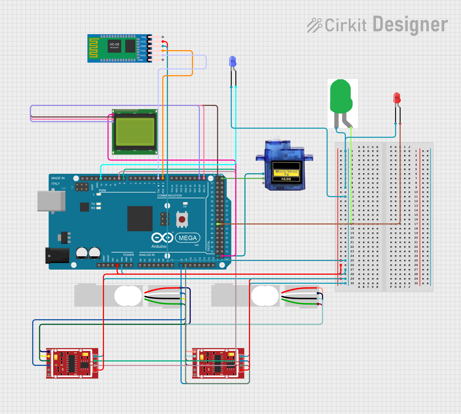

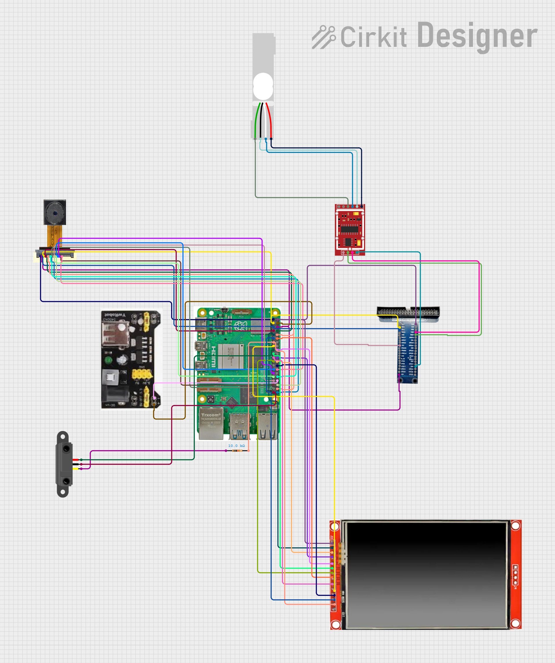
Explore Projects Built with HX711
Common Applications
- Digital weigh scales
- Industrial process control
- Force measurement systems
- Strain gauge sensors
- IoT-based weight monitoring systems
The HX711 is particularly popular in DIY projects and prototyping due to its simplicity and compatibility with microcontrollers like the Arduino.
Technical Specifications
Key Technical Details
| Parameter | Value |
|---|---|
| Manufacturer | Soldered |
| Part ID | Soldered HX711 Breakout |
| ADC Resolution | 24-bit |
| Operating Voltage | 2.6V to 5.5V |
| Typical Operating Current | ~1.5mA |
| Standby Current | <1µA |
| Input Channels | 2 (Channel A and Channel B) |
| Gain Options | 128 (Channel A), 32 (Channel B) |
| Data Rate | 10 Hz or 80 Hz |
| Communication Protocol | Serial (Clock and Data pins) |
| Operating Temperature | -40°C to +85°C |
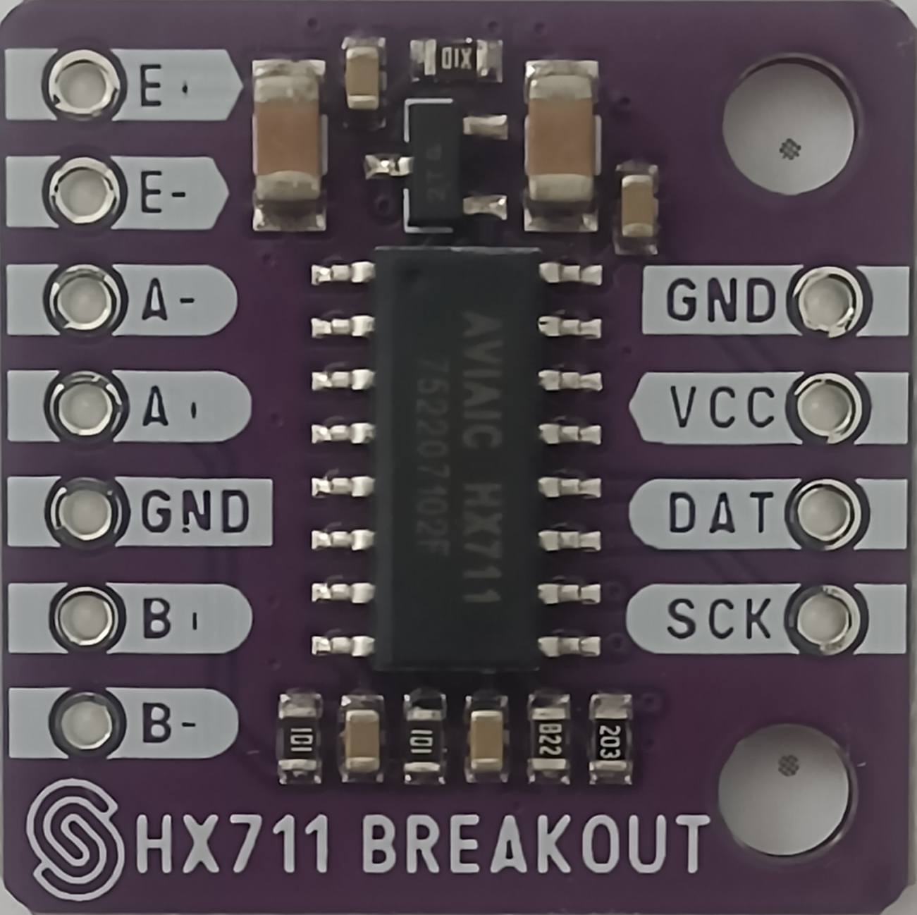
Pin Configuration and Descriptions
The Soldered HX711 Breakout has the following pin layout:
| Pin Name | Pin Type | Description |
|---|---|---|
| VCC | Power | Connect to a 2.6V–5.5V power supply. |
| GND | Ground | Connect to the ground of the circuit. |
| DT | Digital I/O | Data output pin for serial communication. |
| SCK | Digital I/O | Clock input pin for serial communication. |
| E+ | Power | Positive excitation voltage for the load cell (connected to VCC). |
| E- | Power | Negative excitation voltage for the load cell (connected to GND). |
| A+ | Analog In | Positive input for Channel A (connect to the load cell signal output). |
| A- | Analog In | Negative input for Channel A (connect to the load cell signal output). |
| B+ | Analog In | Positive input for Channel B (optional secondary input). |
| B- | Analog In | Negative input for Channel B (optional secondary input). |
Usage Instructions
How to Use the HX711 in a Circuit
- Power the HX711: Connect the VCC pin to a 3.3V or 5V power source and the GND pin to the ground.
- Connect the Load Cell:
- Attach the load cell's excitation wires to the E+ and E- pins.
- Connect the load cell's signal wires to the A+ and A- pins (or B+ and B- for Channel B).
- Connect to a Microcontroller:
- Connect the DT pin to a digital input pin on the microcontroller.
- Connect the SCK pin to a digital output pin on the microcontroller.
- Install a Library (if using Arduino):
- Use the "HX711" library available in the Arduino IDE Library Manager for simplified communication.
- Write Code: Use the library to read data from the HX711 and convert it into meaningful weight or force values.
Important Considerations and Best Practices
- Power Supply: Ensure a stable power supply to avoid noise in the ADC readings.
- Load Cell Calibration: Calibrate the load cell to ensure accurate measurements.
- Shielding: Use shielded cables for the load cell to minimize interference.
- Data Rate: Choose the appropriate data rate (10 Hz for higher accuracy, 80 Hz for faster response).
- Pull-up Resistors: The DT and SCK lines may require pull-up resistors depending on the microcontroller.
Example Arduino Code
Below is an example of how to use the HX711 with an Arduino UNO:
#include "HX711.h" // Include the HX711 library

// Define HX711 pins
#define DT_PIN 3  // Data pin connected to Arduino digital pin 3
#define SCK_PIN 2 // Clock pin connected to Arduino digital pin 2

HX711 scale; // Create an instance of the HX711 class

void setup() {
  Serial.begin(9600); // Initialize serial communication
  scale.begin(DT_PIN, SCK_PIN); // Initialize the HX711 with DT and SCK pins

  Serial.println("Calibrating... Place a known weight on the scale.");
  scale.set_scale(); // Set the scale to default (no calibration factor)
  scale.tare();      // Reset the scale to 0
  delay(5000);       // Wait for user to place a weight
  long known_weight = 100; // Replace with the known weight in grams
  scale.set_scale(scale.get_units() / known_weight); // Calibrate the scale
  Serial.println("Calibration complete.");
}

void loop() {
  // Read and print the weight
  float weight = scale.get_units(); // Get the weight in calibrated units
  Serial.print("Weight: ");
  Serial.print(weight);
  Serial.println(" g");
  delay(500); // Wait 500ms before the next reading
}
Troubleshooting and FAQs
Common Issues and Solutions
No Data Output:
- Ensure the DT and SCK pins are correctly connected to the microcontroller.
- Verify that the HX711 is powered (check VCC and GND connections).
Unstable Readings:
- Use a stable power supply to reduce noise.
- Shield the load cell wires to minimize electromagnetic interference.
- Check for loose connections in the circuit.
Incorrect Weight Measurements:
- Calibrate the load cell properly using a known weight.
- Verify that the load cell is not overloaded or damaged.
Slow Response Time:
- Increase the data rate to 80 Hz by adjusting the SCK pin timing in the code.
FAQs
Q: Can I use the HX711 with a 3.3V microcontroller?
A: Yes, the HX711 operates at 2.6V–5.5V, making it compatible with both 3.3V and 5V systems.
Q: How do I connect multiple load cells to the HX711?
A: The HX711 supports two channels (A and B). You can connect one load cell to each channel, but note that Channel B has a lower gain (32x) compared to Channel A (128x).
Q: What is the maximum weight the HX711 can measure?
A: The maximum weight depends on the load cell used. The HX711 itself does not impose a weight limit but converts the load cell's output into digital data.
Q: Can I use the HX711 for non-weight-related applications?
A: Yes, the HX711 can measure small voltage changes, making it suitable for other sensors like strain gauges or pressure sensors.
This concludes the documentation for the Soldered HX711 Breakout.