Cirkit Designer Logo
Cirkit Designer
Your all-in-one circuit design IDE
Home / 
Component Documentation

How to Use Adafruit AD8495: Examples, Pinouts, and Specs

Image of Adafruit AD8495
Cirkit Designer LogoDesign with Adafruit AD8495 in Cirkit Designer

Introduction

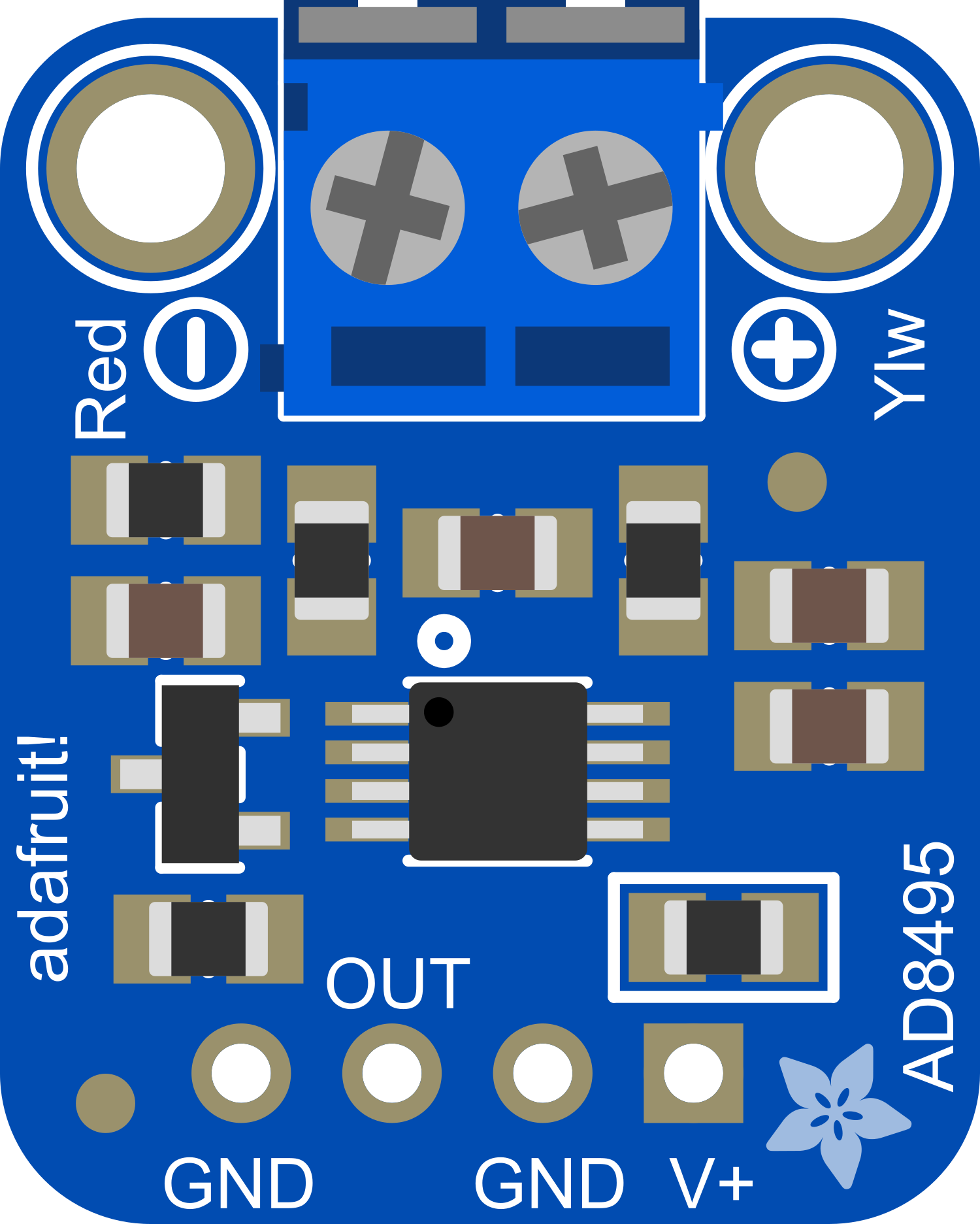
The Adafruit AD8495 is a precision analog output K-type thermocouple amplifier which makes it simple to measure temperatures with a wide range using a type K thermocouple. It is designed to amplify the tiny voltage differences across the thermocouple's leads and convert them into a more easily readable output that correlates with temperature. The module includes cold-junction compensation and an analog output that can be interfaced with analog-to-digital converters (ADCs) on microcontrollers such as the Arduino UNO. This makes the AD8495 an ideal choice for a variety of temperature sensing applications in electronics, industrial systems, and hobbyist projects.

Explore Projects Built with Adafruit AD8495

Use Cirkit Designer to design, explore, and prototype these projects online. Some projects support real-time simulation. Click "Open Project" to start designing instantly!
Battery-Powered Smart Sensor Hub with Adafruit QT Py RP2040
Image of wearable final: A project utilizing Adafruit AD8495 in a practical application
This circuit features an Adafruit QT Py RP2040 microcontroller interfaced with an APDS9960 proximity sensor, an MPU6050 accelerometer and gyroscope, and an OLED display via I2C communication. It also includes a buzzer controlled by the microcontroller and is powered by a 3.7V LiPo battery with a toggle switch for power control.
Cirkit Designer LogoOpen Project in Cirkit Designer
Raspberry Pi 4B-Based Current Monitoring System with I2C OLED Display
Image of Virtual Energy Monitoring Circuit: A project utilizing Adafruit AD8495 in a practical application
This circuit features a Raspberry Pi 4B as the central processing unit, interfaced with an Adafruit ADS1115 16-bit I2C ADC for analog-to-digital conversion and a 0.96" OLED display for visual output. The ADS1115 is connected to a current sensor for measuring electrical current, with the sensor's output and burden pins connected to the ADC's analog input channels. The Raspberry Pi communicates with both the ADC and the OLED display over the I2C bus, using its GPIO2 and GPIO3 pins for data (SDA) and clock (SCL) lines, respectively.
Cirkit Designer LogoOpen Project in Cirkit Designer
Raspberry Pi Zero-Based Sensor Hub with IMU and Flex Resistor
Image of Project: A project utilizing Adafruit AD8495 in a practical application
This circuit integrates a Raspberry Pi Zero with an Adafruit ADS1115 16-bit ADC and an Adafruit BNO085 9-DOF Orientation IMU Fusion sensor. The Raspberry Pi reads analog signals from a flex resistor through the ADC and gathers orientation data from the IMU sensor, enabling it to process both analog and motion data.
Cirkit Designer LogoOpen Project in Cirkit Designer
Raspberry Pi 4B with I2C Current Sensing and OLED Display
Image of iot task 2: A project utilizing Adafruit AD8495 in a practical application
This circuit features a Raspberry Pi 4B as the central processing unit, interfaced with an Adafruit ADS1115 16-bit I2C ADC for analog-to-digital conversion and a 0.96" OLED display for visual output. The ADC is connected to a current sensor for measuring electrical current, with the sensor's output connected to the ADC's AIN0 pin and the burden resistor connected to AIN1. The Raspberry Pi communicates with both the ADC and the OLED display over the I2C bus, using GPIO2 (SDA) and GPIO3 (SCL) for data exchange.
Cirkit Designer LogoOpen Project in Cirkit Designer

Explore Projects Built with Adafruit AD8495

Use Cirkit Designer to design, explore, and prototype these projects online. Some projects support real-time simulation. Click "Open Project" to start designing instantly!
Image of wearable final: A project utilizing Adafruit AD8495 in a practical application
Battery-Powered Smart Sensor Hub with Adafruit QT Py RP2040
This circuit features an Adafruit QT Py RP2040 microcontroller interfaced with an APDS9960 proximity sensor, an MPU6050 accelerometer and gyroscope, and an OLED display via I2C communication. It also includes a buzzer controlled by the microcontroller and is powered by a 3.7V LiPo battery with a toggle switch for power control.
Cirkit Designer LogoOpen Project in Cirkit Designer
Image of Virtual Energy Monitoring Circuit: A project utilizing Adafruit AD8495 in a practical application
Raspberry Pi 4B-Based Current Monitoring System with I2C OLED Display
This circuit features a Raspberry Pi 4B as the central processing unit, interfaced with an Adafruit ADS1115 16-bit I2C ADC for analog-to-digital conversion and a 0.96" OLED display for visual output. The ADS1115 is connected to a current sensor for measuring electrical current, with the sensor's output and burden pins connected to the ADC's analog input channels. The Raspberry Pi communicates with both the ADC and the OLED display over the I2C bus, using its GPIO2 and GPIO3 pins for data (SDA) and clock (SCL) lines, respectively.
Cirkit Designer LogoOpen Project in Cirkit Designer
Image of Project: A project utilizing Adafruit AD8495 in a practical application
Raspberry Pi Zero-Based Sensor Hub with IMU and Flex Resistor
This circuit integrates a Raspberry Pi Zero with an Adafruit ADS1115 16-bit ADC and an Adafruit BNO085 9-DOF Orientation IMU Fusion sensor. The Raspberry Pi reads analog signals from a flex resistor through the ADC and gathers orientation data from the IMU sensor, enabling it to process both analog and motion data.
Cirkit Designer LogoOpen Project in Cirkit Designer
Image of iot task 2: A project utilizing Adafruit AD8495 in a practical application
Raspberry Pi 4B with I2C Current Sensing and OLED Display
This circuit features a Raspberry Pi 4B as the central processing unit, interfaced with an Adafruit ADS1115 16-bit I2C ADC for analog-to-digital conversion and a 0.96" OLED display for visual output. The ADC is connected to a current sensor for measuring electrical current, with the sensor's output connected to the ADC's AIN0 pin and the burden resistor connected to AIN1. The Raspberry Pi communicates with both the ADC and the OLED display over the I2C bus, using GPIO2 (SDA) and GPIO3 (SCL) for data exchange.
Cirkit Designer LogoOpen Project in Cirkit Designer

Technical Specifications

Key Technical Details

  • Supply Voltage (Vcc): 3.3V to 5.5V
  • Output Type: Analog voltage
  • Temperature Measurement Range: -250°C to +750°C (with appropriate thermocouple)
  • Output Voltage Range: 0V to Vcc
  • Accuracy: ±2°C
  • Cold Junction Compensation: Included
  • Interface: Analog

Pin Configuration and Descriptions

Pin Number Name Description
1 V+ Supply voltage input (3.3V to 5.5V)
2 GND Ground connection
3 VOUT Analog voltage output proportional to the temperature
4 TC+ Thermocouple positive connection
5 TC- Thermocouple negative connection

Usage Instructions

Interfacing with an Arduino UNO

  1. Connecting the Module:

    • Connect the V+ pin to the 5V output on the Arduino UNO.
    • Connect the GND pin to one of the GND pins on the Arduino UNO.
    • Connect the VOUT pin to an analog input on the Arduino UNO (e.g., A0).
    • Connect the thermocouple leads to the TC+ and TC- terminals, ensuring correct polarity.
  2. Programming the Arduino:

    • Use the analogRead() function to read the voltage from the AD8495 output.
    • Convert the analog reading to a temperature value using the appropriate conversion factor.

Example Arduino Code

const int thermocouplePin = A0; // AD8495 output connected to A0

void setup() {
  Serial.begin(9600);
}

void loop() {
  int analogValue = analogRead(thermocouplePin);
  float millivolts = (analogValue / 1023.0) * 5000; // Convert to millivolts
  float temperatureC = millivolts / 5; // 5mV per degree Celsius

  Serial.print("Temperature: ");
  Serial.print(temperatureC);
  Serial.println(" C");

  delay(1000); // Wait for 1 second before reading again
}

Important Considerations and Best Practices

  • Ensure that the thermocouple wires are connected with the correct polarity to the module.
  • Avoid placing the AD8495 near heat sources or areas with rapid temperature changes to prevent false readings.
  • Use twisted pair wires for the thermocouple to minimize electrical noise and interference.
  • When using long thermocouple wires, consider shielding and proper grounding to reduce potential signal degradation.

Troubleshooting and FAQs

Common Issues

  • Inaccurate Temperature Readings:

    • Check the thermocouple connections for correct polarity.
    • Verify that the AD8495 is not subjected to significant temperature gradients that could affect the cold-junction compensation.
    • Ensure that the Arduino ADC reference voltage is stable and accurate.
  • No Output Voltage:

    • Confirm that the supply voltage is within the specified range and properly connected.
    • Inspect the thermocouple for any damage or disconnections.

FAQs

Q: Can the AD8495 be used with other types of thermocouples? A: The AD8495 is specifically calibrated for type K thermocouples. Using other types may result in inaccurate readings.

Q: What is the resolution of the temperature measurement? A: The resolution depends on the ADC resolution of the microcontroller. For an Arduino UNO with a 10-bit ADC and a 5V reference, the resolution is approximately 0.488°C.

Q: How can I improve the accuracy of my temperature measurements? A: Use a stable power supply, ensure proper thermocouple connections, and calibrate the system if necessary. Additionally, using a microcontroller with a higher resolution ADC can improve the measurement accuracy.

For further assistance or inquiries, consult the Adafruit AD8495 datasheet and the support forums for community-driven troubleshooting and tips.