How to Use BNO085: Examples, Pinouts, and Specs
Introduction
The BNO085 is a 9-axis absolute orientation sensor that integrates a 3-axis accelerometer, a 3-axis gyroscope, and a 3-axis magnetometer. This sensor is designed to provide highly accurate motion tracking and orientation data. It is widely used in applications such as robotics, drones, augmented reality (AR), virtual reality (VR), and wearable devices. The BNO085 is capable of fusing sensor data internally, reducing the computational load on the host microcontroller.
Explore Projects Built with BNO085


Explore Projects Built with BNO085
Technical Specifications
- Sensor Type: 9-axis absolute orientation sensor
- Interfaces: I²C, SPI, UART
- Operating Voltage: 1.8V to 3.6V
- Current Consumption:
- Typical: 1.3 mA (at 3.3V, accelerometer + gyroscope + magnetometer active)
- Low-power mode: 0.01 mA
- Operating Temperature: -40°C to +85°C
- Output Data: Quaternion, Euler angles, raw sensor data
- Update Rate: Configurable up to 400 Hz
- Package: 3.8 mm x 5.2 mm LGA
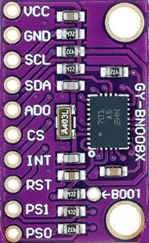
Pin Configuration and Descriptions
The BNO085 has 14 pins. Below is the pinout and description:
| Pin | Name | Type | Description |
|---|---|---|---|
| 1 | VDD | Power | Main power supply (1.8V to 3.6V). |
| 2 | VDDIO | Power | I/O voltage supply (1.8V to 3.6V). |
| 3 | GND | Ground | Ground connection. |
| 4 | PS0 | Input | Protocol selection pin 0. Used to select communication protocol. |
| 5 | PS1 | Input | Protocol selection pin 1. Used to select communication protocol. |
| 6 | RSTN | Input | Active-low reset pin. |
| 7 | INTN | Output | Interrupt pin. Signals data availability or events. |
| 8 | SCL/SCLK | Input | I²C clock or SPI clock, depending on the selected protocol. |
| 9 | SDA/MOSI | Input/Output | I²C data or SPI MOSI, depending on the selected protocol. |
| 10 | SA0/MISO | Input/Output | I²C address selection or SPI MISO, depending on the selected protocol. |
| 11 | CSN | Input | SPI chip select (active low). |
| 12 | BOOTN | Input | Boot mode selection. |
| 13 | NC | - | No connection. |
| 14 | NC | - | No connection. |
Usage Instructions
How to Use the BNO085 in a Circuit
- Power Supply: Connect the VDD and VDDIO pins to a 3.3V power source. Ensure proper decoupling capacitors are placed near the power pins.
- Communication Protocol: Use the PS0 and PS1 pins to select the desired communication protocol:
- I²C: PS0 = 0, PS1 = 0
- SPI: PS0 = 1, PS1 = 0
- UART: PS0 = 0, PS1 = 1
- Pull-Up Resistors: For I²C communication, connect pull-up resistors (typically 4.7 kΩ) to the SDA and SCL lines.
- Interrupt Pin: Connect the INTN pin to a GPIO pin on the host microcontroller to handle interrupts.
- Reset Pin: Optionally, connect the RSTN pin to a GPIO pin for manual reset functionality.
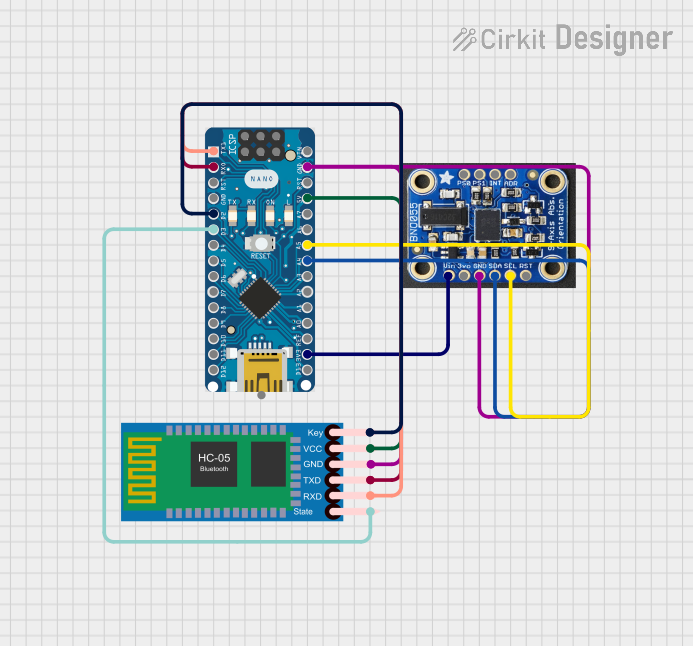
Example: Connecting the BNO085 to an Arduino UNO (I²C)
Below is an example of how to connect the BNO085 to an Arduino UNO using the I²C protocol:
- VDD: Connect to the 3.3V pin on the Arduino.
- VDDIO: Connect to the 3.3V pin on the Arduino.
- GND: Connect to the GND pin on the Arduino.
- SCL: Connect to the A5 pin on the Arduino.
- SDA: Connect to the A4 pin on the Arduino.
- PS0: Connect to GND.
- PS1: Connect to GND.
Arduino Code Example
#include <Wire.h>
#include <Adafruit_Sensor.h>
#include <Adafruit_BNO08x.h>

// Create an instance of the BNO085 sensor
Adafruit_BNO08x bno = Adafruit_BNO08x();

void setup() {
  Serial.begin(115200);
  while (!Serial) {
    delay(10); // Wait for Serial Monitor to open
  }

  Serial.println("Initializing BNO085...");

  // Initialize I2C communication
  if (!bno.begin_I2C()) {
    Serial.println("Failed to initialize BNO085! Check connections.");
    while (1);
  }

  Serial.println("BNO085 initialized successfully!");
  bno.enableReport(BNO_REPORT_ACCELEROMETER); // Enable accelerometer data
}

void loop() {
  sensors_event_t event;

  // Get accelerometer data
  if (bno.getEvent(&event, Adafruit_BNO08x::SENSOR_ACCELEROMETER)) {
    Serial.print("Accel X: ");
    Serial.print(event.acceleration.x);
    Serial.print(" m/s^2, Y: ");
    Serial.print(event.acceleration.y);
    Serial.print(" m/s^2, Z: ");
    Serial.print(event.acceleration.z);
    Serial.println(" m/s^2");
  }

  delay(100); // Delay for readability
}
Important Considerations and Best Practices
- Power Supply: Ensure the BNO085 is powered with a stable voltage within the specified range (1.8V to 3.6V). Avoid voltage spikes.
- Communication Protocol: Select the appropriate protocol based on your application and ensure proper wiring.
- Interrupt Handling: Use the INTN pin to efficiently handle data availability without constant polling.
- Magnetometer Calibration: Perform magnetometer calibration in the intended environment to improve accuracy.
- Placement: Mount the sensor on a stable surface to minimize vibrations and noise.
Troubleshooting and FAQs
Common Issues and Solutions
The sensor is not responding over I²C.
- Check the wiring and ensure pull-up resistors are connected to the SDA and SCL lines.
- Verify the I²C address of the BNO085 (default: 0x4A or 0x4B depending on SA0 pin state).
Incorrect or unstable orientation data.
- Ensure the sensor is mounted securely and away from magnetic interference.
- Perform a magnetometer calibration.
The Arduino code fails to initialize the sensor.
- Double-check the connections and ensure the BNO085 is powered correctly.
- Verify that the Adafruit_BNO08x library is installed and up to date.
The sensor outputs data at an unexpected rate.
- Check the configured update rate in your code and adjust it as needed.
FAQs
Can the BNO085 be used with 5V logic?
- No, the BNO085 operates at 1.8V to 3.6V. Use a level shifter if interfacing with 5V logic.
What is the maximum cable length for I²C communication?
- The maximum length depends on the pull-up resistor values and the I²C clock speed. For reliable communication, keep the cable length under 1 meter.
Does the BNO085 support raw sensor data output?
- Yes, the BNO085 can output raw accelerometer, gyroscope, and magnetometer data in addition to fused orientation data.