How to Use LSM303c 6DOF IMU: Examples, Pinouts, and Specs
Introduction
The LSM303C is a compact 6 Degrees of Freedom (6DOF) Inertial Measurement Unit (IMU) that combines a 3-axis accelerometer and a 3-axis magnetometer. This sensor is capable of providing real-time information about linear acceleration and magnetic field strength along three perpendicular axes. It is widely used in applications such as robotics, navigation, gesture recognition, and motion tracking.
Explore Projects Built with LSM303c 6DOF IMU


Explore Projects Built with LSM303c 6DOF IMU
Common Applications and Use Cases
- Orientation and compass functions in smartphones and tablets
- Navigation systems for drones and unmanned vehicles
- Tilt-compensated compasses for marine and outdoor handheld devices
- Motion detection and analysis in fitness and health monitoring devices
- Stabilization systems in cameras and other handheld equipment
Technical Specifications
Key Technical Details
- Accelerometer Range: ±2/±4/±8 g
- Magnetometer Range: ±16 gauss
- Operating Voltage: 1.9 V to 3.6 V
- Interface: I2C/SPI
- Output Data Rates (ODR): Up to 10 Hz for magnetometer, up to 400 Hz for accelerometer
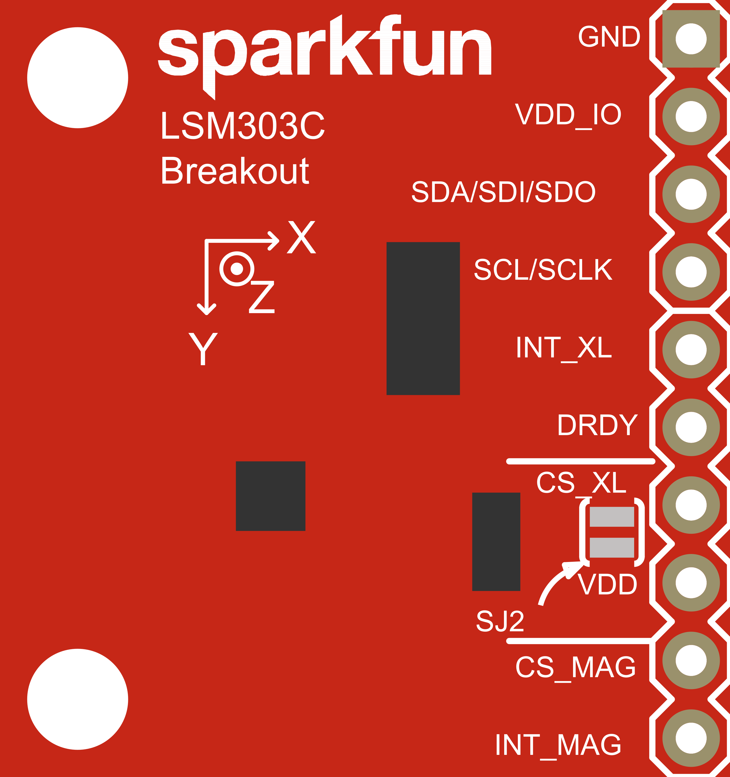
Pin Configuration and Descriptions
| Pin Number | Pin Name | Description |
|---|---|---|
| 1 | VDD | Power supply voltage (1.9V to 3.6V) |
| 2 | GND | Ground |
| 3 | SDA/SDI | I2C data line / SPI serial data input |
| 4 | SCL/SCLK | I2C clock line / SPI serial clock |
| 5 | SA0/SDO | I2C address selection / SPI data output |
| 6 | CS | SPI chip select (active low) |
| 7 | DRDY | Data ready (active high) |
| 8 | INT | Interrupt output |
Usage Instructions
How to Use the Component in a Circuit
- Powering the Device: Connect the VDD pin to a power supply within the specified voltage range and GND to the ground.
- Communication Interface: Choose between I2C or SPI for communication with a microcontroller such as an Arduino UNO.
- Address Selection: For I2C, the SA0/SDO pin can be used to select the device address. For SPI, this pin serves as the data output.
- Data Ready and Interrupts: The DRDY and INT pins can be connected to the microcontroller's GPIO pins to receive alerts when data is ready or when certain thresholds are exceeded.
Important Considerations and Best Practices
- Ensure that the power supply is stable and within the specified voltage range to prevent damage to the sensor.
- Use pull-up resistors on the I2C lines if multiple devices are connected to the bus.
- When using SPI, ensure that the CS pin is driven low before starting communication and driven high after communication ends.
- Place the sensor away from magnetic fields that may interfere with the magnetometer readings.
- Calibrate the magnetometer to account for hard-iron and soft-iron distortions for accurate readings.
Example Code for Arduino UNO
#include <Wire.h>
#include <LSM303C.h>

LSM303C imu;

void setup() {
  Wire.begin(); // Initialize I2C
  Serial.begin(9600); // Start serial communication at 9600 baud
  if (!imu.begin()) {
    Serial.println("Failed to initialize LSM303C");
    while (1);
  }
}

void loop() {
  imu.read(); // Read the accelerometer and magnetometer values

  // Print the acceleration values
  Serial.print("Accel X: "); Serial.print(imu.ax); Serial.print(" ");
  Serial.print("Accel Y: "); Serial.print(imu.ay); Serial.print(" ");
  Serial.print("Accel Z: "); Serial.println(imu.az);

  // Print the magnetometer values
  Serial.print("Mag X: "); Serial.print(imu.mx); Serial.print(" ");
  Serial.print("Mag Y: "); Serial.print(imu.my); Serial.print(" ");
  Serial.print("Mag Z: "); Serial.println(imu.mz);

  delay(100); // Delay for readability
}
Note: This example assumes the use of a library (LSM303C.h) that abstracts the complexity of interfacing with the sensor. Make sure to install the library before compiling the code.
Troubleshooting and FAQs
Common Issues Users Might Face
- No Data Output: Ensure that the sensor is properly powered and that the I2C/SPI connections are correct.
- Inaccurate Readings: Calibrate the sensor, especially the magnetometer, to account for environmental factors.
- Intermittent Communication: Check for loose connections and ensure that the pull-up resistors are correctly installed on the I2C lines.
Solutions and Tips for Troubleshooting
- Verify the power supply voltage with a multimeter.
- Use the
Wirelibrary'sbeginTransmission()andendTransmission()functions to check for successful communication over I2C. - For SPI, ensure that the timing requirements are met and that the CS pin is being used correctly.
FAQs
Q: Can the LSM303C be used with a 5V microcontroller like the Arduino UNO? A: Yes, but ensure that the voltage levels on the I2C/SPI lines are shifted down to be within the sensor's operating range.
Q: How can I change the measurement range of the accelerometer or magnetometer? A: This can typically be done through the sensor's registers. Refer to the LSM303C datasheet and use the appropriate library functions to configure the ranges.
Q: What is the default I2C address of the LSM303C? A: The default I2C address depends on the voltage level applied to the SA0/SDO pin. Check the datasheet for the specific addresses.
Q: How do I interpret the raw data from the sensor? A: The raw data needs to be converted to meaningful units. The library used in the example code often provides functions to do this conversion.