Cirkit Designer Logo
Cirkit Designer
Your all-in-one circuit design IDE
Home / 
Component Documentation

How to Use keypad 3x4: Examples, Pinouts, and Specs

Image of keypad 3x4
Cirkit Designer LogoDesign with keypad 3x4 in Cirkit Designer

Introduction

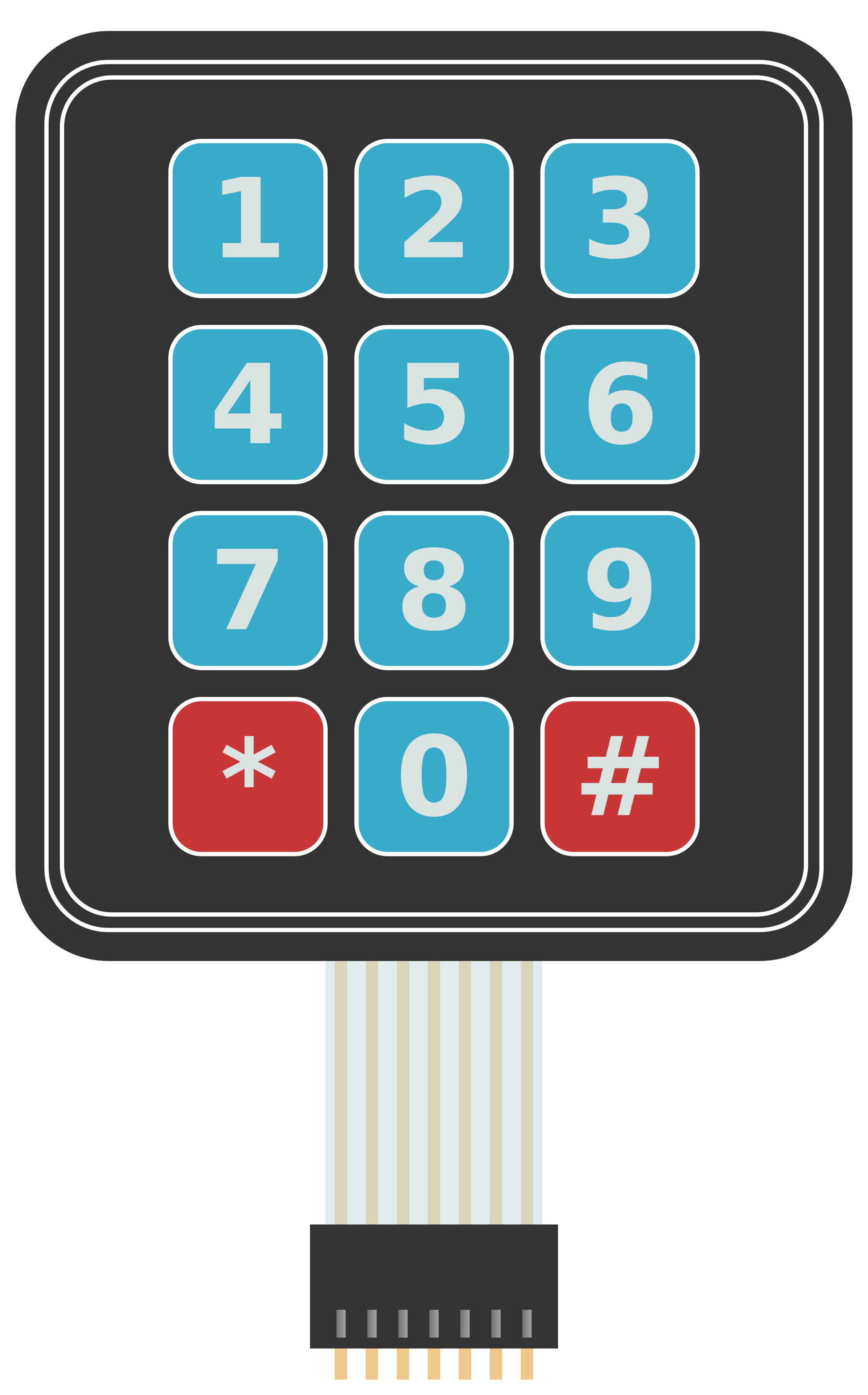
The 3x4 matrix keypad is a compact and versatile input device consisting of 12 buttons arranged in 3 rows and 4 columns. Each button represents a unique key, making it ideal for applications requiring user input, such as password entry, menu navigation, or numeric data entry. This keypad is widely used in embedded systems, home automation, security systems, and other electronic devices.

Explore Projects Built with keypad 3x4

Use Cirkit Designer to design, explore, and prototype these projects online. Some projects support real-time simulation. Click "Open Project" to start designing instantly!
Arduino UNO Keypad-Controlled LED and Buzzer System with RTC and Bluetooth
Image of Uni: A project utilizing keypad 3x4 in a practical application
This circuit is an Arduino-based keypad interface system that reads input from a 4x4 membrane matrix keypad and displays the pressed key on the serial monitor. It also includes a real-time clock (RTC) module, a Bluetooth module, and visual indicators using red and green LEDs. Additionally, a buzzer is controlled via an NPN transistor for audio feedback.
Cirkit Designer LogoOpen Project in Cirkit Designer
Arduino UNO Keypad Input Logger
Image of 4x4 Keypad (Simulation Demo): A project utilizing keypad 3x4 in a practical application
This circuit integrates a 4x4 keypad with an Arduino UNO to create a simple input interface. The Arduino reads key presses from the keypad and outputs the corresponding character to the Serial Monitor, allowing for user interaction and data entry.
Cirkit Designer LogoOpen Project in Cirkit Designer
Arduino UNO Membrane Keypad Interface
Image of Connect Adafruit 3x4 Matrix Keypad to Arduino Uno: A project utilizing keypad 3x4 in a practical application
This circuit connects a 3x4 membrane matrix keypad to an Arduino UNO microcontroller. The Arduino is programmed to detect and report keypress events from the keypad over a serial connection at a baud rate of 9600. The purpose of this circuit is to interface with the keypad and provide a way to input data into a system or control a device.
Cirkit Designer LogoOpen Project in Cirkit Designer
Arduino UNO Based 4x4 Keypad Interface
Image of keypad: A project utilizing keypad 3x4 in a practical application
This circuit connects a 4x4 membrane matrix keypad to an Arduino UNO microcontroller. The rows (R1-R4) and columns (C1-C4) of the keypad are wired to digital pins D9-D2 on the Arduino, respectively. The purpose of the circuit is to allow the Arduino to detect and process key presses from the keypad, which can be used for user input in various applications.
Cirkit Designer LogoOpen Project in Cirkit Designer

Explore Projects Built with keypad 3x4

Use Cirkit Designer to design, explore, and prototype these projects online. Some projects support real-time simulation. Click "Open Project" to start designing instantly!
Image of Uni: A project utilizing keypad 3x4 in a practical application
Arduino UNO Keypad-Controlled LED and Buzzer System with RTC and Bluetooth
This circuit is an Arduino-based keypad interface system that reads input from a 4x4 membrane matrix keypad and displays the pressed key on the serial monitor. It also includes a real-time clock (RTC) module, a Bluetooth module, and visual indicators using red and green LEDs. Additionally, a buzzer is controlled via an NPN transistor for audio feedback.
Cirkit Designer LogoOpen Project in Cirkit Designer
Image of 4x4 Keypad (Simulation Demo): A project utilizing keypad 3x4 in a practical application
Arduino UNO Keypad Input Logger
This circuit integrates a 4x4 keypad with an Arduino UNO to create a simple input interface. The Arduino reads key presses from the keypad and outputs the corresponding character to the Serial Monitor, allowing for user interaction and data entry.
Cirkit Designer LogoOpen Project in Cirkit Designer
Image of Connect Adafruit 3x4 Matrix Keypad to Arduino Uno: A project utilizing keypad 3x4 in a practical application
Arduino UNO Membrane Keypad Interface
This circuit connects a 3x4 membrane matrix keypad to an Arduino UNO microcontroller. The Arduino is programmed to detect and report keypress events from the keypad over a serial connection at a baud rate of 9600. The purpose of this circuit is to interface with the keypad and provide a way to input data into a system or control a device.
Cirkit Designer LogoOpen Project in Cirkit Designer
Image of keypad: A project utilizing keypad 3x4 in a practical application
Arduino UNO Based 4x4 Keypad Interface
This circuit connects a 4x4 membrane matrix keypad to an Arduino UNO microcontroller. The rows (R1-R4) and columns (C1-C4) of the keypad are wired to digital pins D9-D2 on the Arduino, respectively. The purpose of the circuit is to allow the Arduino to detect and process key presses from the keypad, which can be used for user input in various applications.
Cirkit Designer LogoOpen Project in Cirkit Designer

Common Applications

  • Security systems (e.g., PIN entry for door locks)
  • Home automation control panels
  • Vending machines
  • Calculator-style input devices
  • Menu navigation in embedded systems

Technical Specifications

The 3x4 keypad operates as a matrix, where each button press connects a specific row and column. This design minimizes the number of pins required for interfacing.

Key Specifications

Parameter Value
Number of Buttons 12 (3 rows x 4 columns)
Operating Voltage 3.3V to 5V
Maximum Current 20mA per key press
Button Lifespan ~1,000,000 presses
Dimensions ~7cm x 5cm x 0.5cm
Connector Type 7-pin header

Pin Configuration

The keypad has 7 pins: 3 for rows and 4 for columns. The table below describes each pin:

Pin Number Label Description
1 R1 Row 1
2 R2 Row 2
3 R3 Row 3
4 C1 Column 1
5 C2 Column 2
6 C3 Column 3
7 C4 Column 4

Usage Instructions

Connecting the Keypad

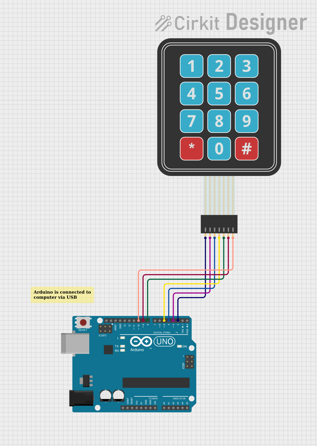
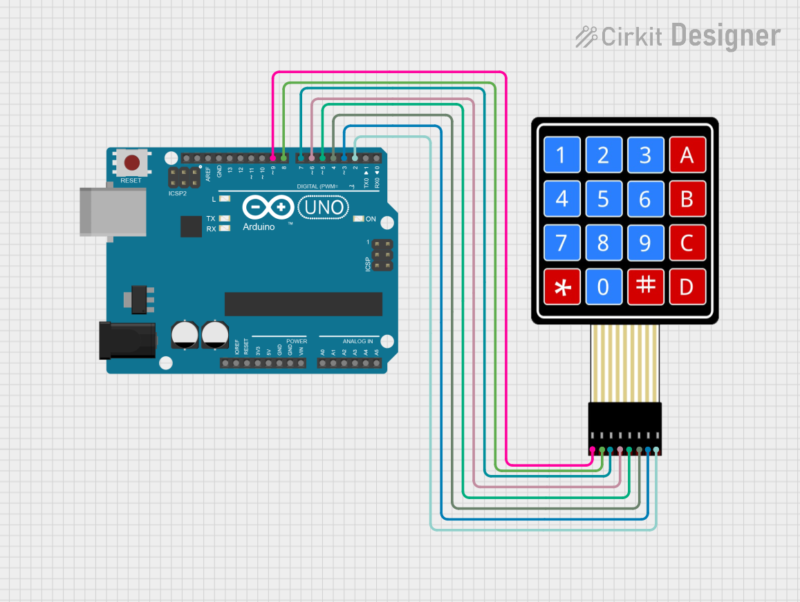
  1. Wiring: Connect the keypad's 7 pins to a microcontroller or development board (e.g., Arduino UNO). Use pull-up or pull-down resistors if necessary to stabilize the signal.
  2. Matrix Scanning: The microcontroller scans the rows and columns to detect which button is pressed. This is done by setting rows as outputs and columns as inputs (or vice versa).
  3. Libraries: For Arduino, the Keypad library simplifies interfacing with the keypad.

Example Arduino Code

Below is an example of how to use the 3x4 keypad with an Arduino UNO:

#include <Keypad.h>

// Define the rows and columns of the keypad
const byte ROWS = 3; // 3 rows
const byte COLS = 4; // 4 columns

// Define the keymap for the keypad
char keys[ROWS][COLS] = {
  {'1', '2', '3', 'A'},
  {'4', '5', '6', 'B'},
  {'7', '8', '9', 'C'},
  {'*', '0', '#', 'D'}
};

// Define the row and column pins connected to the Arduino
byte rowPins[ROWS] = {9, 8, 7};    // Connect to R1, R2, R3
byte colPins[COLS] = {6, 5, 4, 3}; // Connect to C1, C2, C3, C4

// Create the Keypad object
Keypad keypad = Keypad(makeKeymap(keys), rowPins, colPins, ROWS, COLS);

void setup() {
  Serial.begin(9600); // Initialize serial communication
  Serial.println("Keypad Test: Press a key");
}

void loop() {
  char key = keypad.getKey(); // Check if a key is pressed

  if (key) {
    // Print the pressed key to the Serial Monitor
    Serial.print("Key Pressed: ");
    Serial.println(key);
  }
}

Best Practices

  • Debouncing: Use software debouncing to avoid false key presses caused by mechanical bounce.
  • Pull-up Resistors: Enable internal pull-up resistors on input pins to ensure stable readings.
  • Keypad Placement: Place the keypad in an accessible location for the user, and ensure it is securely mounted.

Troubleshooting and FAQs

Common Issues

  1. No Key Press Detected

    • Cause: Incorrect wiring or loose connections.
    • Solution: Double-check the wiring and ensure all connections are secure.
  2. Multiple Keys Detected

    • Cause: Electrical noise or improper debouncing.
    • Solution: Implement software debouncing and verify the circuit design.
  3. Incorrect Key Mapping

    • Cause: Mismatch between the physical keypad layout and the keymap in the code.
    • Solution: Verify the keymap array in the code matches the keypad's layout.
  4. Keys Not Responding

    • Cause: Damaged keypad or insufficient power supply.
    • Solution: Test the keypad with a multimeter and ensure the power supply meets the requirements.

FAQs

Q: Can I use the 3x4 keypad with a Raspberry Pi?
A: Yes, the keypad can be used with a Raspberry Pi. You can use GPIO pins and libraries like gpiozero or RPI.GPIO to interface with the keypad.

Q: How do I extend the keypad's cable length?
A: Use shielded cables to reduce noise and interference. Avoid excessively long cables to maintain signal integrity.

Q: Can I use the keypad for alphanumeric input?
A: Yes, you can map the keys to alphanumeric characters and implement logic in your code to handle multi-character input.

Q: Is the keypad waterproof?
A: Standard 3x4 keypads are not waterproof. For outdoor or wet environments, use a waterproof keypad or protective enclosure.