How to Use DC-DC Buck Converter: Examples, Pinouts, and Specs
Introduction
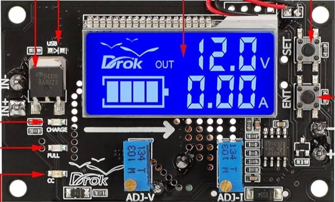
The DC-DC Buck Converter by DROK is a highly efficient power electronics device designed to step down voltage from a higher level to a lower level. It achieves this through a combination of switching elements, inductors, and diodes, ensuring minimal energy loss during the conversion process. This component is widely used in applications where regulated lower voltage is required from a higher voltage source.
Explore Projects Built with DC-DC Buck Converter


Explore Projects Built with DC-DC Buck Converter
Common Applications and Use Cases
- Powering low-voltage devices (e.g., microcontrollers, sensors) from higher voltage sources.
- Battery-powered systems requiring efficient voltage regulation.
- Renewable energy systems, such as solar panels, to regulate output voltage.
- Automotive electronics for stepping down car battery voltage.
- Industrial and consumer electronics requiring stable DC power.
Technical Specifications
Key Technical Details
| Parameter | Value |
|---|---|
| Input Voltage Range | 6V to 36V |
| Output Voltage Range | 1.25V to 32V (adjustable) |
| Maximum Output Current | 5A (with proper heat dissipation) |
| Output Power | Up to 75W |
| Efficiency | Up to 96% (depending on input/output ratio) |
| Switching Frequency | 180 kHz |
| Operating Temperature | -40°C to +85°C |
| Dimensions | 61mm x 26mm x 15mm |
Pin Configuration and Descriptions
| Pin Name | Description |
|---|---|
| VIN+ | Positive input voltage terminal (connect to the higher voltage source). |
| VIN- | Negative input voltage terminal (connect to the ground of the voltage source). |
| VOUT+ | Positive output voltage terminal (connect to the load). |
| VOUT- | Negative output voltage terminal (connect to the ground of the load). |
| Adjustment Potentiometer | Used to adjust the output voltage. Rotate clockwise to increase voltage and counterclockwise to decrease voltage. |
Usage Instructions
How to Use the Component in a Circuit
Connect the Input Voltage:
- Connect the positive terminal of your power source to the
VIN+pin. - Connect the ground of your power source to the
VIN-pin. - Ensure the input voltage is within the specified range (6V to 36V).
- Connect the positive terminal of your power source to the
Connect the Output Load:
- Connect the positive terminal of your load to the
VOUT+pin. - Connect the ground of your load to the
VOUT-pin.
- Connect the positive terminal of your load to the
Adjust the Output Voltage:
- Use the onboard potentiometer to set the desired output voltage.
- Measure the output voltage using a multimeter while adjusting the potentiometer.
Verify Connections:
- Double-check all connections to ensure proper polarity and secure connections.
Power On:
- Turn on the input power source and verify the output voltage is as expected.
Important Considerations and Best Practices
- Heat Dissipation: For currents above 3A, ensure proper heat dissipation by attaching a heatsink or using active cooling.
- Input Voltage: Always ensure the input voltage is higher than the desired output voltage.
- Load Requirements: Do not exceed the maximum output current (5A) or power rating (75W).
- Polarity: Double-check the polarity of all connections to avoid damage to the converter.
- Ripple and Noise: Use additional capacitors at the input and output terminals to reduce voltage ripple and noise.
Example: Using with an Arduino UNO
The DC-DC Buck Converter can be used to power an Arduino UNO from a 12V power source. Below is an example circuit and code:
Circuit Connections
- Connect the 12V power source to the
VIN+andVIN-pins of the buck converter. - Adjust the output voltage to 5V using the potentiometer.
- Connect the
VOUT+pin to the Arduino's5Vpin. - Connect the
VOUT-pin to the Arduino'sGNDpin.
Example Code
// Example code to blink an LED using Arduino UNO powered by the DC-DC Buck Converter

const int ledPin = 13; // Pin connected to the onboard LED

void setup() {
  pinMode(ledPin, OUTPUT); // Set the LED pin as an output
}

void loop() {
  digitalWrite(ledPin, HIGH); // Turn the LED on
  delay(1000);                // Wait for 1 second
  digitalWrite(ledPin, LOW);  // Turn the LED off
  delay(1000);                // Wait for 1 second
}
Troubleshooting and FAQs
Common Issues and Solutions
| Issue | Possible Cause | Solution |
|---|---|---|
| No output voltage | Incorrect wiring or polarity | Verify all connections and ensure correct polarity. |
| Output voltage is unstable | Insufficient input voltage or high load current | Ensure input voltage is within range and reduce the load current if needed. |
| Overheating | High current draw or inadequate heat dissipation | Add a heatsink or active cooling to the converter. |
| Cannot adjust output voltage | Faulty potentiometer or incorrect input voltage | Check the potentiometer and ensure input voltage is higher than output. |
| High output ripple or noise | Insufficient filtering | Add capacitors (e.g., 100µF electrolytic and 0.1µF ceramic) at the output. |
FAQs
Can I use this converter to power a Raspberry Pi?
- Yes, but ensure the output voltage is set to 5V and the current requirement of the Raspberry Pi is met.
What happens if I reverse the input polarity?
- The converter does not have reverse polarity protection. Reversing the input polarity may damage the device.
Can I use this converter with a solar panel?
- Yes, as long as the solar panel's output voltage is within the input range of the converter.
How do I reduce noise in sensitive applications?
- Use additional filtering capacitors and keep the wiring as short as possible to minimize noise.
What is the efficiency of the converter at low loads?
- The efficiency is typically lower at very low loads but remains above 80% in most cases.
This documentation provides a comprehensive guide to using the DROK DC-DC Buck Converter effectively and safely. For further assistance, refer to the manufacturer's datasheet or contact technical support.