How to Use ICS 43434: Examples, Pinouts, and Specs
Introduction
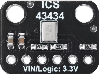
The ICS 43434 is a low-power, high-performance MEMS (Micro-Electro-Mechanical Systems) microphone designed for audio applications. Manufactured by Anyone, this microphone features a digital Pulse Density Modulation (PDM) output, making it ideal for integration into modern digital systems. Its compact size, low power consumption, and high signal-to-noise ratio (SNR) make it suitable for use in smartphones, tablets, laptops, and other portable devices. The ICS 43434 is optimized for clear sound capture with minimal noise, ensuring high-quality audio performance.
Explore Projects Built with ICS 43434


Explore Projects Built with ICS 43434
Common Applications
- Smartphones and tablets
- Wearable devices
- Voice-controlled systems (e.g., smart speakers)
- Audio recording equipment
- IoT devices with voice input functionality
Technical Specifications
Key Technical Details
| Parameter | Value |
|---|---|
| Supply Voltage (VDD) | 1.62V to 3.63V |
| Signal-to-Noise Ratio (SNR) | 65 dB (typical) |
| Acoustic Overload Point | 120 dB SPL |
| Sensitivity | -26 dBFS ±1 dB |
| Frequency Response | 50 Hz to 20 kHz |
| Output Format | Digital PDM |
| Current Consumption | 650 µA (typical) |
| Operating Temperature Range | -40°C to +85°C |
| Package Dimensions | 3.50 mm × 2.65 mm × 0.98 mm |
Pin Configuration and Descriptions
The ICS 43434 has a 5-pin configuration. The table below describes each pin:
| Pin Name | Pin Number | Description |
|---|---|---|
| VDD | 1 | Power supply input (1.62V to 3.63V). |
| GND | 2 | Ground connection. |
| DATA | 3 | Digital PDM output signal. |
| CLK | 4 | Clock input for PDM interface. |
| SEL | 5 | Channel select (left/right). |
Usage Instructions
How to Use the ICS 43434 in a Circuit
- Power Supply: Connect the VDD pin to a stable power source within the range of 1.62V to 3.63V. Connect the GND pin to the ground of the circuit.
- Clock Signal: Provide a clock signal (typically 1 MHz to 3.25 MHz) to the CLK pin. This clock drives the PDM output.
- Digital Output: The DATA pin outputs the PDM signal, which can be processed by a microcontroller or digital signal processor (DSP).
- Channel Selection: Use the SEL pin to configure the microphone as either the left or right channel in a stereo setup:
- Connect SEL to GND for the left channel.
- Connect SEL to VDD for the right channel.
Important Considerations
- Decoupling Capacitor: Place a 0.1 µF decoupling capacitor close to the VDD pin to reduce noise and ensure stable operation.
- Clock Signal Quality: Ensure the clock signal is clean and within the specified frequency range to avoid distortion in the PDM output.
- PCB Layout: Minimize the trace length for the DATA and CLK lines to reduce signal degradation and noise interference.
- Acoustic Design: Position the microphone aperture away from sources of mechanical vibration or airflow to maintain audio quality.
Example: Connecting ICS 43434 to an Arduino UNO
The ICS 43434 can be interfaced with an Arduino UNO using a PDM-to-PCM library for audio processing. Below is an example setup and code:
Circuit Connections
| ICS 43434 Pin | Arduino UNO Pin |
|---|---|
| VDD | 3.3V |
| GND | GND |
| DATA | Digital Pin 2 |
| CLK | Digital Pin 3 |
| SEL | GND (Left Channel) or 3.3V (Right Channel) |
Arduino Code
#include <PDM.h> // Include the PDM library for audio processing

// Define pins for the ICS 43434
#define PDM_DATA_PIN 2 // Pin connected to the DATA pin of ICS 43434
#define PDM_CLK_PIN 3  // Pin connected to the CLK pin of ICS 43434

// Buffer to store audio samples
#define BUFFER_SIZE 256
int16_t audioBuffer[BUFFER_SIZE];

// Callback function to handle incoming PDM data
void onPDMData() {
  int bytesAvailable = PDM.available(); // Check available bytes
  PDM.read(audioBuffer, bytesAvailable); // Read PDM data into buffer
}

void setup() {
  // Initialize serial communication for debugging
  Serial.begin(9600);
  while (!Serial);

  // Configure PDM microphone
  if (!PDM.begin(1, 16000)) { // Mono channel, 16 kHz sample rate
    Serial.println("Failed to start PDM!");
    while (1);
  }

  // Set the PDM data callback
  PDM.onReceive(onPDMData);

  Serial.println("PDM microphone initialized.");
}

void loop() {
  // Process audio data in the main loop
  // (e.g., send data to a computer or perform real-time analysis)
}
Troubleshooting and FAQs
Common Issues and Solutions
No Output Signal from DATA Pin
- Cause: Missing or incorrect clock signal.
- Solution: Verify that the CLK pin is receiving a clean clock signal within the specified frequency range (1 MHz to 3.25 MHz).
Distorted Audio Output
- Cause: Incorrect power supply voltage or noisy clock signal.
- Solution: Ensure the VDD pin is supplied with a stable voltage (1.62V to 3.63V). Use a decoupling capacitor near the VDD pin. Check the quality of the clock signal.
Microphone Not Responding
- Cause: Incorrect SEL pin configuration.
- Solution: Verify the SEL pin connection. Connect it to GND for the left channel or VDD for the right channel.
High Noise in Output
- Cause: Poor PCB layout or external interference.
- Solution: Minimize trace lengths for DATA and CLK lines. Keep the microphone away from sources of mechanical vibration or airflow.
FAQs
Q: Can the ICS 43434 operate at 5V?
A: No, the ICS 43434 operates within a supply voltage range of 1.62V to 3.63V. Exceeding this range may damage the component.
Q: Is the ICS 43434 suitable for outdoor use?
A: The ICS 43434 is designed for indoor use. If used outdoors, ensure it is protected from moisture and extreme environmental conditions.
Q: Can I use multiple ICS 43434 microphones in a single system?
A: Yes, you can use multiple microphones. Configure the SEL pin of each microphone to assign it as the left or right channel in a stereo setup.
This concludes the documentation for the ICS 43434 MEMS microphone. For further assistance, refer to the manufacturer's datasheet or contact technical support.