How to Use Integrated Servo Motor iSV Series: Examples, Pinouts, and Specs
Introduction
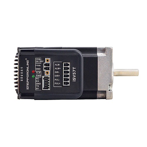
The Integrated Servo Motor iSV Series (Model: ISV57T-090S), manufactured by Stepper Online, is a compact and efficient motor that combines a servo motor with an integrated controller. This all-in-one design eliminates the need for external drivers, simplifying wiring and reducing system complexity. The motor provides precise motion control and feedback, making it ideal for applications requiring high accuracy and reliability.
Explore Projects Built with Integrated Servo Motor iSV Series
Explore Projects Built with Integrated Servo Motor iSV Series
Common Applications and Use Cases
- Robotics and automation systems
- CNC machines and 3D printers
- Conveyor systems
- Industrial machinery
- Medical devices requiring precise motion control
Technical Specifications
Key Technical Details
| Parameter | Value |
|---|---|
| Manufacturer Part ID | ISV57T-090S |
| Motor Type | Integrated Servo Motor |
| Rated Voltage | 24-50 VDC |
| Rated Current | 4.0 A |
| Holding Torque | 0.9 Nm (127.5 oz-in) |
| Step Angle | 1.8° |
| Communication Interface | RS232/RS485 |
| Control Mode | Position, Speed, and Torque |
| Feedback | 1000-line Incremental Encoder |
| Dimensions (L x W x H) | 57 x 57 x 90 mm |
| Weight | 0.8 kg |
Pin Configuration and Descriptions
The motor's connector pinout is as follows:
Power Connector
| Pin Number | Signal Name | Description |
|---|---|---|
| 1 | V+ | Positive power supply (24-50 VDC) |
| 2 | GND | Ground |
Communication Connector (RS232/RS485)
| Pin Number | Signal Name | Description |
|---|---|---|
| 1 | TX+ | Transmit Data Positive |
| 2 | TX- | Transmit Data Negative |
| 3 | RX+ | Receive Data Positive |
| 4 | RX- | Receive Data Negative |
I/O Connector
| Pin Number | Signal Name | Description |
|---|---|---|
| 1 | IN1 | Programmable Input 1 |
| 2 | IN2 | Programmable Input 2 |
| 3 | OUT1 | Programmable Output 1 |
| 4 | OUT2 | Programmable Output 2 |
Usage Instructions
How to Use the Component in a Circuit
- Power Supply: Connect a DC power supply (24-50 VDC) to the power connector. Ensure the power supply can provide sufficient current (at least 4 A) for the motor's operation.
- Communication: Use the RS232 or RS485 interface to communicate with the motor. Configure the communication parameters (e.g., baud rate) as per your system requirements.
- Control Signals: Use the programmable I/O pins to interface with external devices or sensors.
- Mounting: Secure the motor to your system using the provided mounting holes. Ensure proper alignment to avoid mechanical stress.
Important Considerations and Best Practices
- Power Supply: Use a regulated power supply to avoid voltage fluctuations that could damage the motor.
- Heat Dissipation: Ensure adequate ventilation or heat sinking to prevent overheating during prolonged operation.
- Wiring: Keep communication and power wires separate to minimize electrical noise.
- Encoder Feedback: Use the encoder feedback for closed-loop control to achieve precise positioning and speed regulation.
Arduino UNO Example Code
The following example demonstrates how to control the motor using an Arduino UNO via RS485 communication. A suitable RS485-to-TTL module is required for interfacing.
#include <SoftwareSerial.h>

// Define RS485 communication pins
#define RS485_TX 10  // Arduino pin connected to RS485 TX
#define RS485_RX 11  // Arduino pin connected to RS485 RX
#define DE_PIN 8     // Driver Enable pin for RS485 module

SoftwareSerial rs485(RS485_RX, RS485_TX);

void setup() {
  pinMode(DE_PIN, OUTPUT);
  digitalWrite(DE_PIN, LOW); // Set RS485 to receive mode
  rs485.begin(9600);         // Initialize RS485 communication at 9600 baud

  Serial.begin(9600);        // Initialize Serial Monitor
  Serial.println("iSV57T-090S Motor Control");
}

void loop() {
  // Example: Send a command to set motor speed
  digitalWrite(DE_PIN, HIGH); // Set RS485 to transmit mode
  rs485.write(0x01);          // Device address
  rs485.write(0x06);          // Function code (write single register)
  rs485.write(0x00);          // Register address high byte
  rs485.write(0x01);          // Register address low byte
  rs485.write(0x00);          // Data high byte (speed value)
  rs485.write(0x64);          // Data low byte (speed value, e.g., 100)
  rs485.write(0xD8);          // CRC high byte
  rs485.write(0xF0);          // CRC low byte
  digitalWrite(DE_PIN, LOW);  // Set RS485 to receive mode

  delay(1000); // Wait for 1 second before sending the next command
}
Note: Replace the command values with those specific to your application. Refer to the motor's communication protocol for detailed command structure.
Troubleshooting and FAQs
Common Issues and Solutions
Motor Not Responding:
- Verify the power supply voltage and current ratings.
- Check the communication wiring and ensure proper RS232/RS485 connections.
- Confirm that the motor's address and baud rate match the controller's settings.
Overheating:
- Ensure proper ventilation or use a heat sink.
- Reduce the motor's load or duty cycle if operating continuously.
Erratic Movement:
- Check for electrical noise in the wiring.
- Verify encoder feedback connections and ensure proper alignment.
Communication Errors:
- Use shielded cables for RS485 communication.
- Verify the CRC and command structure in your communication protocol.
FAQs
Q1: Can the motor operate without an external controller?
A1: Yes, the integrated controller allows standalone operation. However, external controllers can be used for advanced control.
Q2: What is the maximum cable length for RS485 communication?
A2: RS485 supports cable lengths up to 1200 meters, but shorter lengths are recommended for high-speed communication.
Q3: How do I reset the motor to factory settings?
A3: Refer to the manufacturer's user manual for the reset procedure, typically involving specific commands via RS232/RS485.
Q4: Can I use this motor with a battery-powered system?
A4: Yes, as long as the battery provides a stable voltage within the 24-50 VDC range and sufficient current.