How to Use TMC5160: Examples, Pinouts, and Specs
Introduction
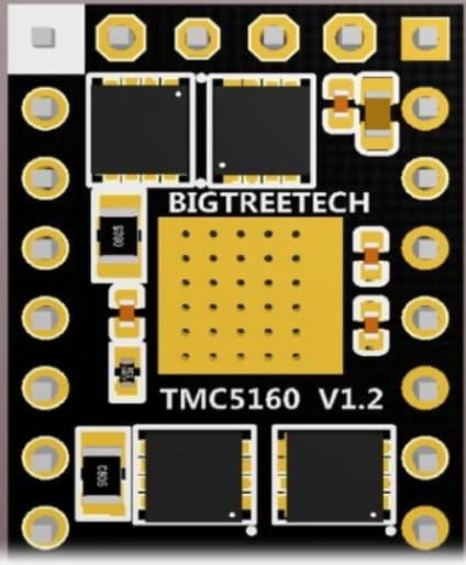
The TMC5160, manufactured by Yklhsocneg (Part ID: 500353763), is a high-performance stepper motor driver designed for precise and efficient control of stepper motors. It integrates advanced features such as microstepping, integrated current sensing, and a wide range of programmable settings, making it ideal for applications requiring smooth motion and high precision.
Explore Projects Built with TMC5160


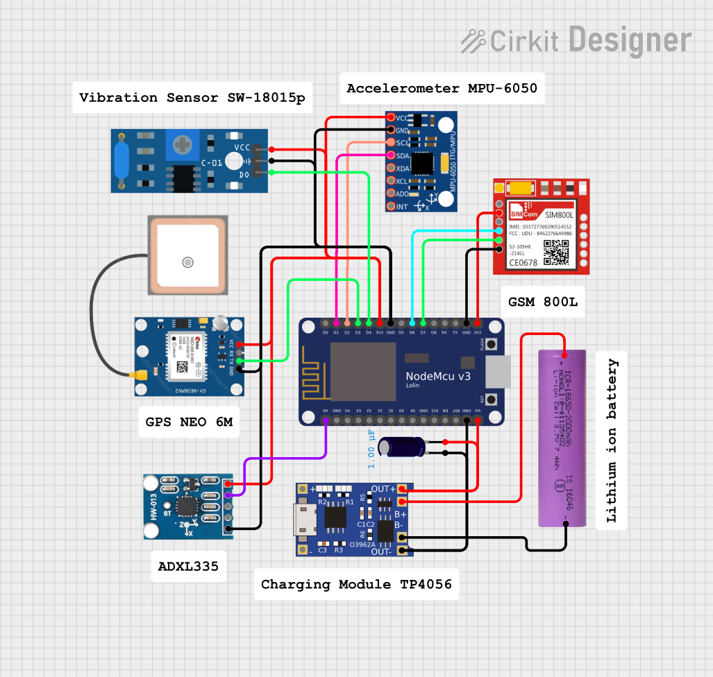
Explore Projects Built with TMC5160
Common Applications and Use Cases
- 3D printers
- CNC machines
- Robotics
- Industrial automation
- Precision positioning systems
Technical Specifications
The TMC5160 is a versatile and powerful stepper motor driver. Below are its key technical details:
Key Technical Details
| Parameter | Value |
|---|---|
| Supply Voltage (VM) | 8V to 60V |
| Logic Voltage (VIO) | 3.3V or 5V |
| Maximum Motor Current | Up to 20A peak (with proper cooling) |
| Microstepping Resolution | Up to 256 microsteps per full step |
| Communication Interface | SPI |
| Integrated Features | Current sensing, stall detection, and more |
| Operating Temperature | -40°C to +125°C |
Pin Configuration and Descriptions
The TMC5160 comes in a 48-pin QFN package. Below is a summary of its pin configuration:
| Pin Number | Pin Name | Description |
|---|---|---|
| 1 | VM | Motor power supply input (8V to 60V) |
| 2 | GND | Ground |
| 3 | VIO | Logic voltage input (3.3V or 5V) |
| 4 | SPI_MOSI | SPI data input |
| 5 | SPI_MISO | SPI data output |
| 6 | SPI_SCK | SPI clock input |
| 7 | SPI_CS | SPI chip select |
| 8 | ENN | Enable input (active low) |
| 9 | STEP | Step pulse input |
| 10 | DIR | Direction control input |
| 11 | DIAG0 | Diagnostic output 0 |
| 12 | DIAG1 | Diagnostic output 1 |
| 13-48 | Various | Motor outputs, configuration pins, etc. |
Refer to the manufacturer's datasheet for a complete pinout and detailed descriptions.
Usage Instructions
The TMC5160 is designed for easy integration into stepper motor control systems. Below are the steps and best practices for using this component:
How to Use the TMC5160 in a Circuit
- Power Supply: Connect the motor power supply (VM) to the VM pin. Ensure the voltage is within the 8V to 60V range.
- Logic Voltage: Provide a 3.3V or 5V logic voltage to the VIO pin.
- SPI Communication: Connect the SPI interface (MOSI, MISO, SCK, CS) to your microcontroller for configuration and control.
- Motor Connections: Connect the stepper motor coils to the appropriate motor output pins.
- Control Signals: Use the STEP and DIR pins to control the motor's movement and direction.
- Cooling: If operating at high currents, ensure proper cooling (e.g., heatsinks or fans) to prevent overheating.
Important Considerations and Best Practices
- Current Limiting: Configure the current limit using the SPI interface to protect the motor and driver.
- Microstepping: Use the programmable microstepping feature to achieve smoother motion and higher precision.
- Stall Detection: Enable stall detection to monitor motor performance and prevent damage.
- Decoupling Capacitors: Place decoupling capacitors close to the VM and VIO pins to reduce noise and ensure stable operation.
- Thermal Management: Monitor the driver's temperature and implement cooling solutions if necessary.
Example Code for Arduino UNO
Below is an example of how to interface the TMC5160 with an Arduino UNO using SPI:
#include <SPI.h>

// Define SPI pins for Arduino UNO
#define CS_PIN 10  // Chip Select pin
#define STEP_PIN 9 // Step pin
#define DIR_PIN 8  // Direction pin

void setup() {
  // Initialize SPI communication
  SPI.begin();
  pinMode(CS_PIN, OUTPUT);
  pinMode(STEP_PIN, OUTPUT);
  pinMode(DIR_PIN, OUTPUT);

  // Set initial states
  digitalWrite(CS_PIN, HIGH); // Deselect TMC5160
  digitalWrite(STEP_PIN, LOW);
  digitalWrite(DIR_PIN, LOW);

  // Configure TMC5160 via SPI
  configureTMC5160();
}

void loop() {
  // Example: Rotate motor in one direction
  digitalWrite(DIR_PIN, HIGH); // Set direction
  for (int i = 0; i < 200; i++) { // 200 steps
    digitalWrite(STEP_PIN, HIGH);
    delayMicroseconds(500); // Adjust for speed
    digitalWrite(STEP_PIN, LOW);
    delayMicroseconds(500);
  }
}

void configureTMC5160() {
  digitalWrite(CS_PIN, LOW); // Select TMC5160
  SPI.transfer(0x80); // Example: Write to a register (address 0x00)
  SPI.transfer(0x00); // Example: Data to write
  digitalWrite(CS_PIN, HIGH); // Deselect TMC5160
}
Troubleshooting and FAQs
Common Issues and Solutions
Motor Not Moving
- Cause: Incorrect wiring or insufficient power supply.
- Solution: Verify all connections and ensure the power supply meets the voltage and current requirements.
Overheating
- Cause: High current settings or inadequate cooling.
- Solution: Reduce the current limit via SPI and improve cooling with heatsinks or fans.
No SPI Communication
- Cause: Incorrect SPI wiring or configuration.
- Solution: Check the SPI connections and ensure the microcontroller's SPI settings match the TMC5160's requirements.
Stall Detection Not Working
- Cause: Incorrect configuration or motor parameters.
- Solution: Verify the stall detection settings and ensure the motor parameters are correctly configured.
FAQs
Q: Can the TMC5160 drive a unipolar stepper motor?
A: No, the TMC5160 is designed for bipolar stepper motors.
Q: What is the maximum microstepping resolution?
A: The TMC5160 supports up to 256 microsteps per full step.
Q: How do I set the current limit?
A: The current limit can be configured via the SPI interface by writing to the appropriate register.
Q: Is the TMC5160 compatible with 5V logic?
A: Yes, the TMC5160 supports both 3.3V and 5V logic levels.
For additional support, refer to the manufacturer's datasheet or contact Yklhsocneg.