How to Use LCD 20X4: Examples, Pinouts, and Specs
Introduction
The LCD 20x4 is a Liquid Crystal Display module capable of displaying 20 characters per line across 4 lines. Manufactured by Arduino with the part ID "UNO," this display is widely used in embedded systems for presenting text and simple graphics. It is ideal for applications requiring a clear and compact display interface, such as control panels, measurement devices, and DIY electronics projects.
Explore Projects Built with LCD 20X4


Explore Projects Built with LCD 20X4
Common Applications and Use Cases
- Home automation systems
- Industrial control panels
- Weather stations
- Robotics and IoT projects
- Educational and prototyping purposes
Technical Specifications
The LCD 20x4 module is designed to operate efficiently with microcontrollers like the Arduino UNO. Below are its key technical details:
Key Technical Details
| Parameter | Specification |
|---|---|
| Display Type | 20x4 Character LCD |
| Interface | Parallel (4-bit or 8-bit) or I2C |
| Operating Voltage | 4.7V to 5.3V |
| Operating Current | 1mA (without backlight) |
| Backlight Voltage | 4.2V to 4.6V |
| Backlight Current | 120mA (typical) |
| Character Size | 5x8 dot matrix |
| Operating Temperature | -20°C to +70°C |
| Dimensions | 98mm x 60mm x 12mm |
Pin Configuration and Descriptions
The LCD 20x4 module typically has 16 pins for parallel communication. If using an I2C adapter, only 4 pins are required.
Parallel Interface Pinout
| Pin Number | Pin Name | Description |
|---|---|---|
| 1 | VSS | Ground (0V) |
| 2 | VDD | Power supply (4.7V to 5.3V) |
| 3 | VO | Contrast adjustment (connect to potentiometer) |
| 4 | RS | Register Select (0: Command, 1: Data) |
| 5 | RW | Read/Write (0: Write, 1: Read) |
| 6 | E | Enable signal (starts data read/write) |
| 7-14 | D0-D7 | Data pins (D0-D3 optional in 4-bit mode) |
| 15 | A (LED+) | Backlight anode (connect to +5V via resistor) |
| 16 | K (LED-) | Backlight cathode (connect to GND) |
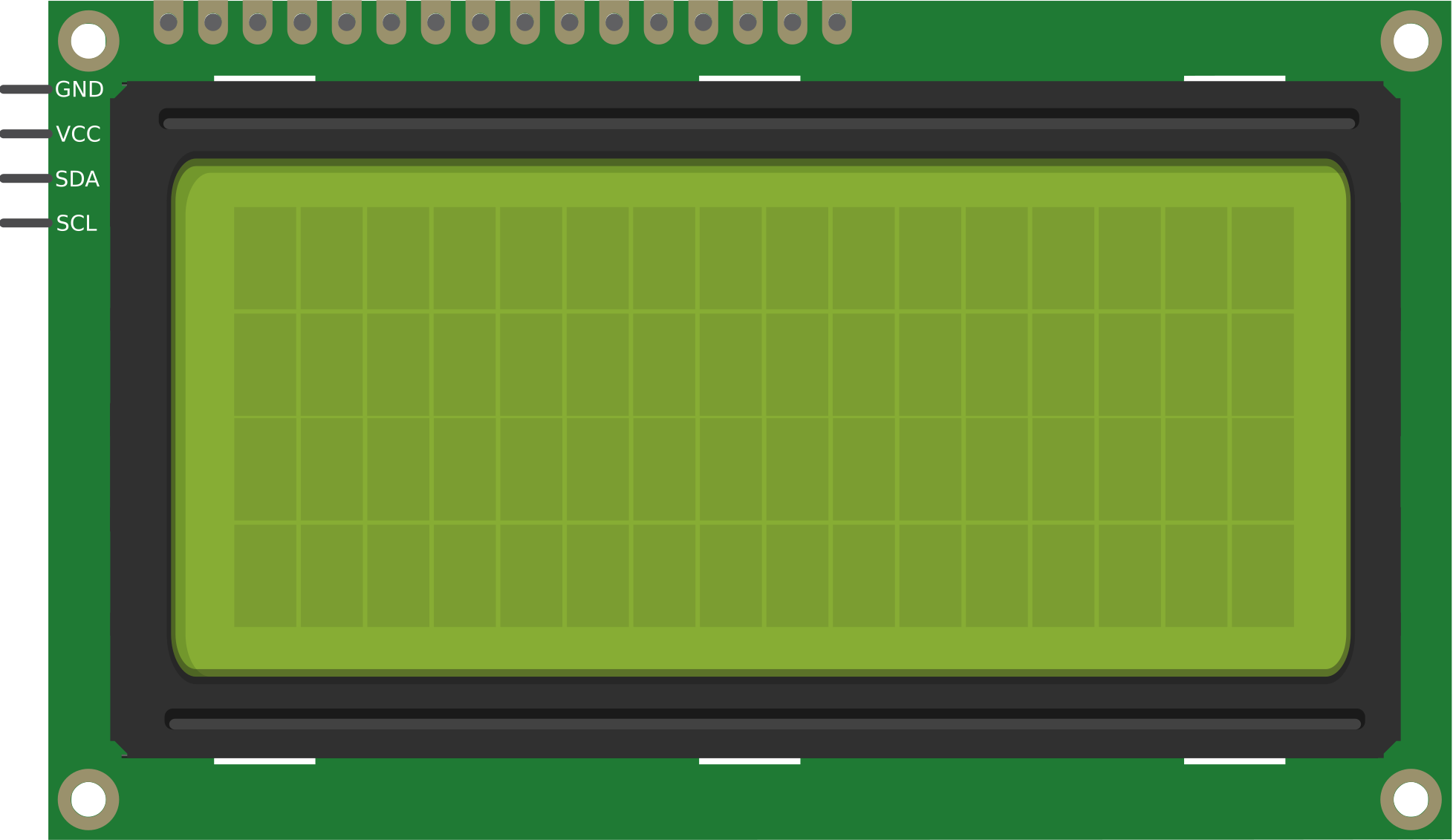
I2C Interface Pinout (with Adapter)
| Pin Number | Pin Name | Description |
|---|---|---|
| 1 | GND | Ground (0V) |
| 2 | VCC | Power supply (4.7V to 5.3V) |
| 3 | SDA | Serial Data Line |
| 4 | SCL | Serial Clock Line |
Usage Instructions
The LCD 20x4 can be used in either parallel or I2C mode. Below are the steps for using it with an Arduino UNO in I2C mode, which is the most common and efficient setup.
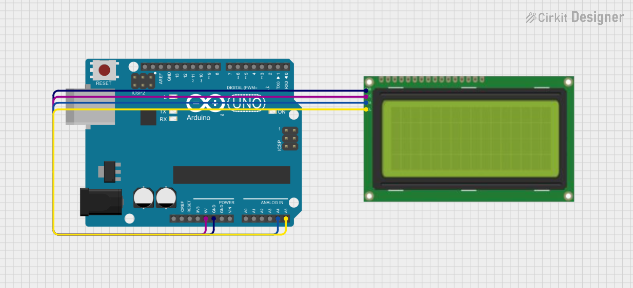
Connecting the LCD 20x4 to Arduino UNO (I2C Mode)
- Attach an I2C adapter to the LCD module.
- Connect the pins as follows:
- GND to Arduino GND
- VCC to Arduino 5V
- SDA to Arduino A4
- SCL to Arduino A5
- Install the
LiquidCrystal_I2Clibrary in the Arduino IDE:- Go to Sketch > Include Library > Manage Libraries.
- Search for "LiquidCrystal_I2C" and install it.
Example Code
The following code demonstrates how to display text on the LCD 20x4 using the Arduino UNO:
#include <Wire.h>
#include <LiquidCrystal_I2C.h>

// Initialize the LCD with I2C address 0x27 and dimensions 20x4
LiquidCrystal_I2C lcd(0x27, 20, 4);

void setup() {
  lcd.begin(); // Initialize the LCD
  lcd.backlight(); // Turn on the backlight

  // Display text on the LCD
  lcd.setCursor(0, 0); // Set cursor to column 0, row 0
  lcd.print("Hello, World!"); // Print text on the first line

  lcd.setCursor(0, 1); // Set cursor to column 0, row 1
  lcd.print("LCD 20x4 Demo"); // Print text on the second line

  lcd.setCursor(0, 2); // Set cursor to column 0, row 2
  lcd.print("Arduino UNO"); // Print text on the third line

  lcd.setCursor(0, 3); // Set cursor to column 0, row 3
  lcd.print("I2C Interface"); // Print text on the fourth line
}

void loop() {
  // No actions in the loop
}
Important Considerations and Best Practices
- Contrast Adjustment: Use a 10kΩ potentiometer connected to the VO pin to adjust the display contrast.
- Backlight Resistor: If the backlight is too bright, use a current-limiting resistor (e.g., 220Ω) on the A (LED+) pin.
- I2C Address: The default I2C address is usually
0x27or0x3F. Use an I2C scanner sketch to confirm the address if needed. - Power Supply: Ensure a stable 5V power supply to avoid flickering or dimming.
Troubleshooting and FAQs
Common Issues and Solutions
No Display on the LCD
- Check the power connections (VCC and GND).
- Adjust the contrast using the potentiometer connected to the VO pin.
- Verify the I2C address and update the code if necessary.
Flickering or Dim Backlight
- Ensure the backlight is connected to a stable 5V supply.
- Add a current-limiting resistor to the backlight anode (A/LED+).
Incorrect or Garbled Characters
- Verify the data connections (SDA and SCL for I2C, or D0-D7 for parallel).
- Ensure the correct library and initialization parameters are used.
I2C Communication Issues
- Use an I2C scanner sketch to detect the LCD's address.
- Check the pull-up resistors on the SDA and SCL lines (typically 4.7kΩ).
FAQs
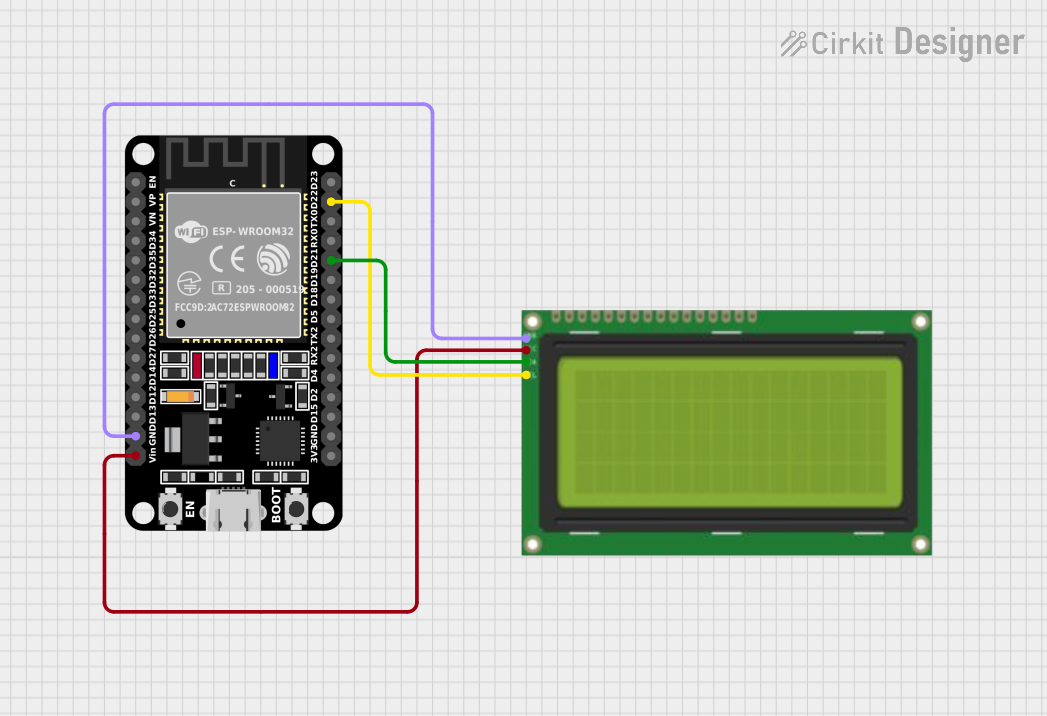
Q: Can I use the LCD 20x4 with a 3.3V microcontroller?
A: Yes, but you will need a level shifter for the data lines and a 3.3V-compatible I2C adapter.
Q: How do I display custom characters?
A: Use the createChar() function in the LiquidCrystal_I2C library to define and display custom characters.
Q: Can I use the LCD 20x4 without an I2C adapter?
A: Yes, you can use the parallel interface, but it requires more pins and wiring.
Q: What is the maximum viewing angle of the LCD?
A: The typical viewing angle is ±45° horizontally and ±30° vertically.
By following this documentation, you can effectively integrate the LCD 20x4 into your projects and troubleshoot common issues with ease.