How to Use GREEN LED: Examples, Pinouts, and Specs
Introduction
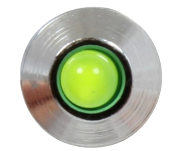
The GREEN LED (Manufacturer: AC, Part ID: LED) is a light-emitting diode that emits green light when an electric current passes through it. This component is widely used in electronic circuits for visual indicators, status displays, and decorative lighting. Its low power consumption, long lifespan, and high efficiency make it a popular choice for a variety of applications.
Explore Projects Built with GREEN LED
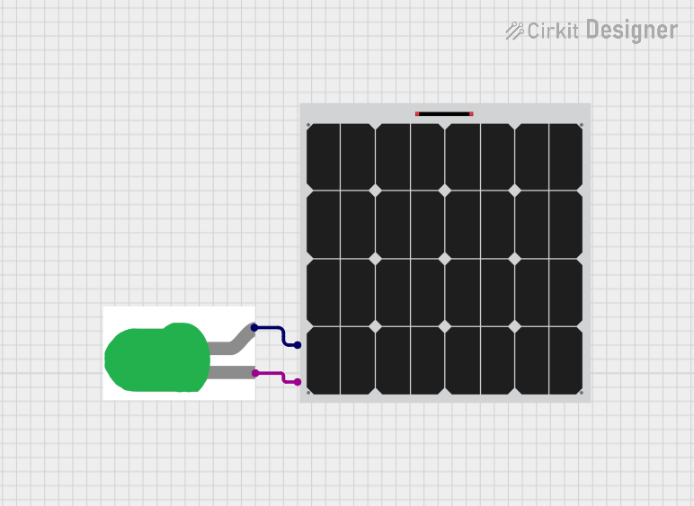
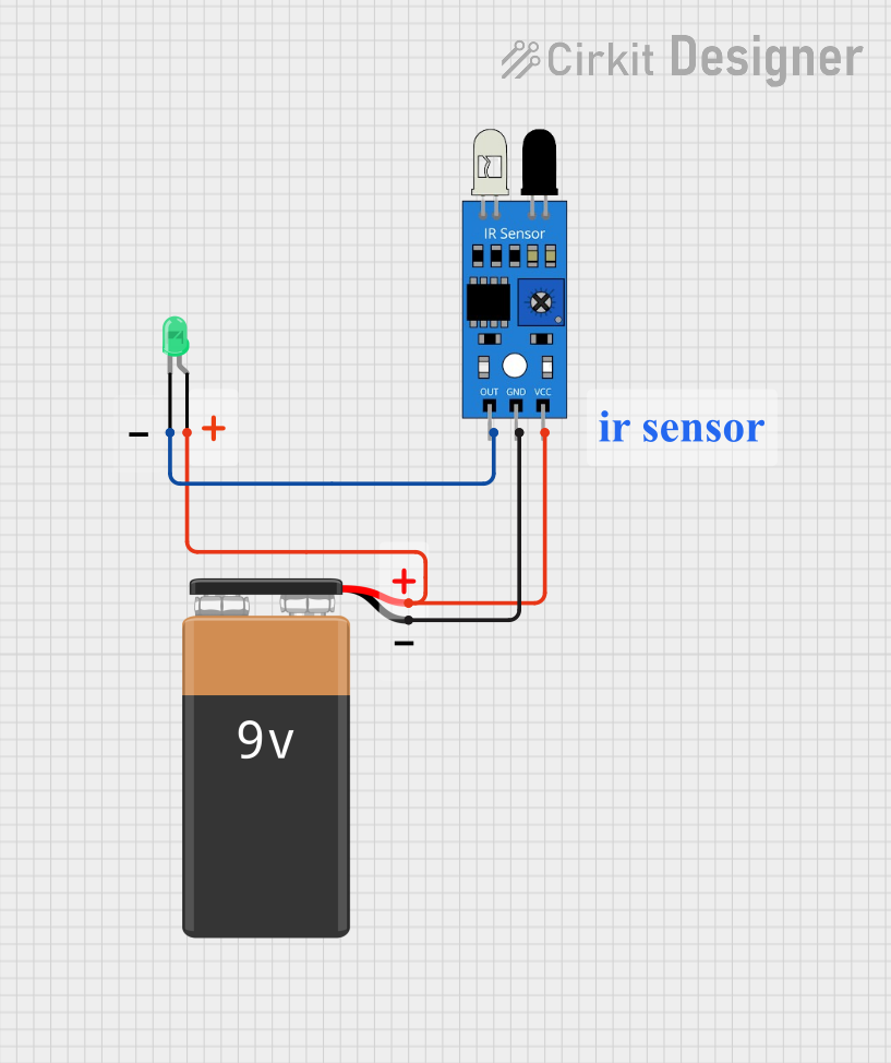

Explore Projects Built with GREEN LED
Common Applications and Use Cases
- Power and status indicators in electronic devices
- Signal and warning lights
- Decorative and ambient lighting
- Displays in consumer electronics
- Educational and DIY electronics projects
Technical Specifications
The following table outlines the key technical specifications of the GREEN LED:
| Parameter | Value |
|---|---|
| Manufacturer | AC |
| Part ID | LED |
| Forward Voltage (Vf) | 2.0V to 2.4V |
| Forward Current (If) | 20mA (typical) |
| Maximum Current (If max) | 30mA |
| Wavelength | 520nm to 530nm (green light) |
| Viewing Angle | 20° to 30° |
| Power Dissipation | 60mW (maximum) |
| Operating Temperature | -40°C to +85°C |
| Storage Temperature | -40°C to +100°C |
Pin Configuration and Descriptions
The GREEN LED has two pins: the anode (positive) and the cathode (negative). The table below describes the pin configuration:
| Pin Name | Description | Identification |
|---|---|---|
| Anode | Positive terminal; connects to V+ | Longer leg of the LED |
| Cathode | Negative terminal; connects to GND | Shorter leg of the LED, or flat edge on the casing |
Usage Instructions
How to Use the GREEN LED in a Circuit
Determine the Resistor Value: To prevent damage to the LED, always use a current-limiting resistor in series with the LED. The resistor value can be calculated using Ohm's Law: [ R = \frac{V_{supply} - V_f}{I_f} ] Where:
- (V_{supply}) is the supply voltage
- (V_f) is the forward voltage of the LED (2.2V typical)
- (I_f) is the desired forward current (20mA typical)
For example, if (V_{supply} = 5V): [ R = \frac{5V - 2.2V}{0.02A} = 140\Omega ] Use the nearest standard resistor value (e.g., 150Ω).
Connect the LED:
- Connect the anode (longer leg) to the positive side of the power supply through the resistor.
- Connect the cathode (shorter leg) to the ground (GND).
Test the Circuit: Power the circuit and observe the green light emitted by the LED.
Important Considerations and Best Practices
- Polarity: LEDs are polarized components. Ensure the anode is connected to the positive voltage and the cathode to ground.
- Current Limiting: Always use a resistor to limit the current through the LED. Exceeding the maximum current rating can permanently damage the LED.
- Heat Management: While the GREEN LED generates minimal heat, ensure proper ventilation in high-density circuits.
- Series and Parallel Configurations: For multiple LEDs, calculate resistor values for each configuration to ensure consistent brightness.
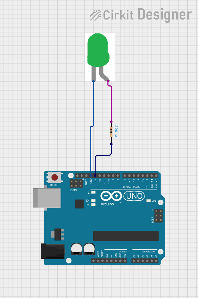
Example: Connecting a GREEN LED to an Arduino UNO
Below is an example of how to connect and control a GREEN LED using an Arduino UNO:
Circuit Setup
- Connect the anode of the GREEN LED to digital pin 9 on the Arduino through a 150Ω resistor.
- Connect the cathode of the LED to the GND pin on the Arduino.
Arduino Code
// GREEN LED Example with Arduino UNO
// This code blinks a GREEN LED connected to pin 9 every second.

const int ledPin = 9; // Define the pin connected to the LED

void setup() {
  pinMode(ledPin, OUTPUT); // Set the LED pin as an output
}

void loop() {
  digitalWrite(ledPin, HIGH); // Turn the LED on
  delay(1000);                // Wait for 1 second
  digitalWrite(ledPin, LOW);  // Turn the LED off
  delay(1000);                // Wait for 1 second
}
Troubleshooting and FAQs
Common Issues and Solutions
LED Does Not Light Up:
Cause: Incorrect polarity.
Solution: Ensure the anode is connected to the positive voltage and the cathode to ground.
Cause: No current-limiting resistor or incorrect resistor value.
Solution: Verify the resistor value and ensure it is connected in series with the LED.
LED is Dim:
- Cause: Insufficient current.
- Solution: Check the resistor value and ensure the supply voltage is adequate.
LED Burns Out Quickly:
- Cause: Excessive current.
- Solution: Use a resistor to limit the current to the recommended value (20mA).
LED Flickers:
- Cause: Unstable power supply or loose connections.
- Solution: Check the power supply and ensure all connections are secure.
FAQs
Q1: Can I connect the GREEN LED directly to a 5V power supply?
A1: No, connecting the LED directly to a power supply without a resistor will result in excessive current, potentially damaging the LED.
Q2: How do I know the polarity of the LED?
A2: The anode (positive) is the longer leg, and the cathode (negative) is the shorter leg or the side with a flat edge on the casing.
Q3: Can I use the GREEN LED with a 3.3V power supply?
A3: Yes, but you still need a current-limiting resistor. Calculate the resistor value based on the supply voltage and forward voltage of the LED.
Q4: What happens if I exceed the maximum current rating?
A4: Exceeding the maximum current rating can cause the LED to overheat and fail permanently.
This concludes the documentation for the GREEN LED.