How to Use L298 Dual H Bridge Motor Speed Controller: Examples, Pinouts, and Specs
Introduction
The L298 Dual H Bridge Motor Speed Controller is an integrated circuit designed to control the direction and speed of DC motors. It is capable of driving two motors simultaneously in either direction, which makes it a popular choice for robotics, automation projects, and any application requiring bidirectional control of motors with speed variation.
Explore Projects Built with L298 Dual H Bridge Motor Speed Controller
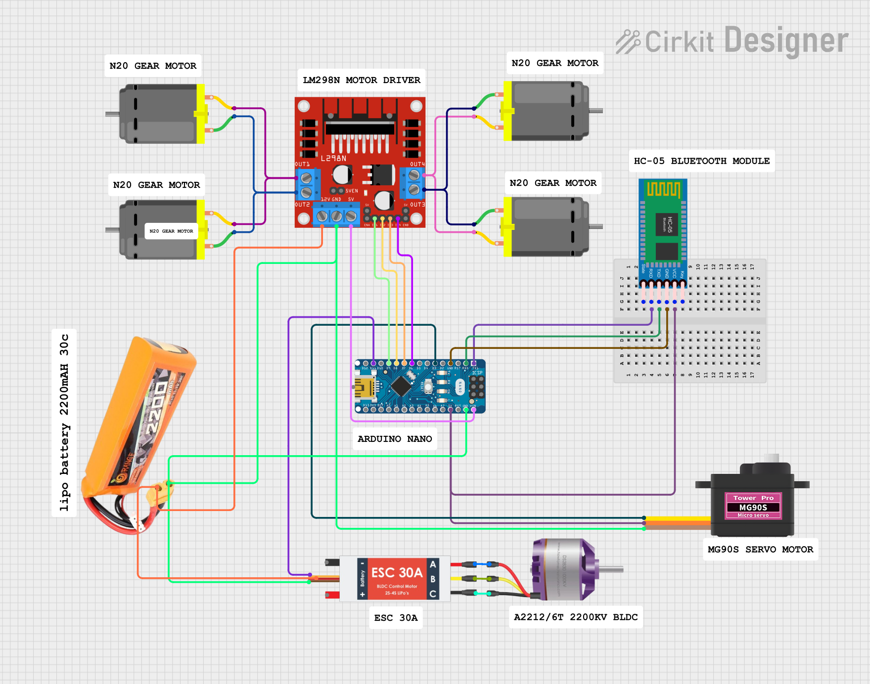
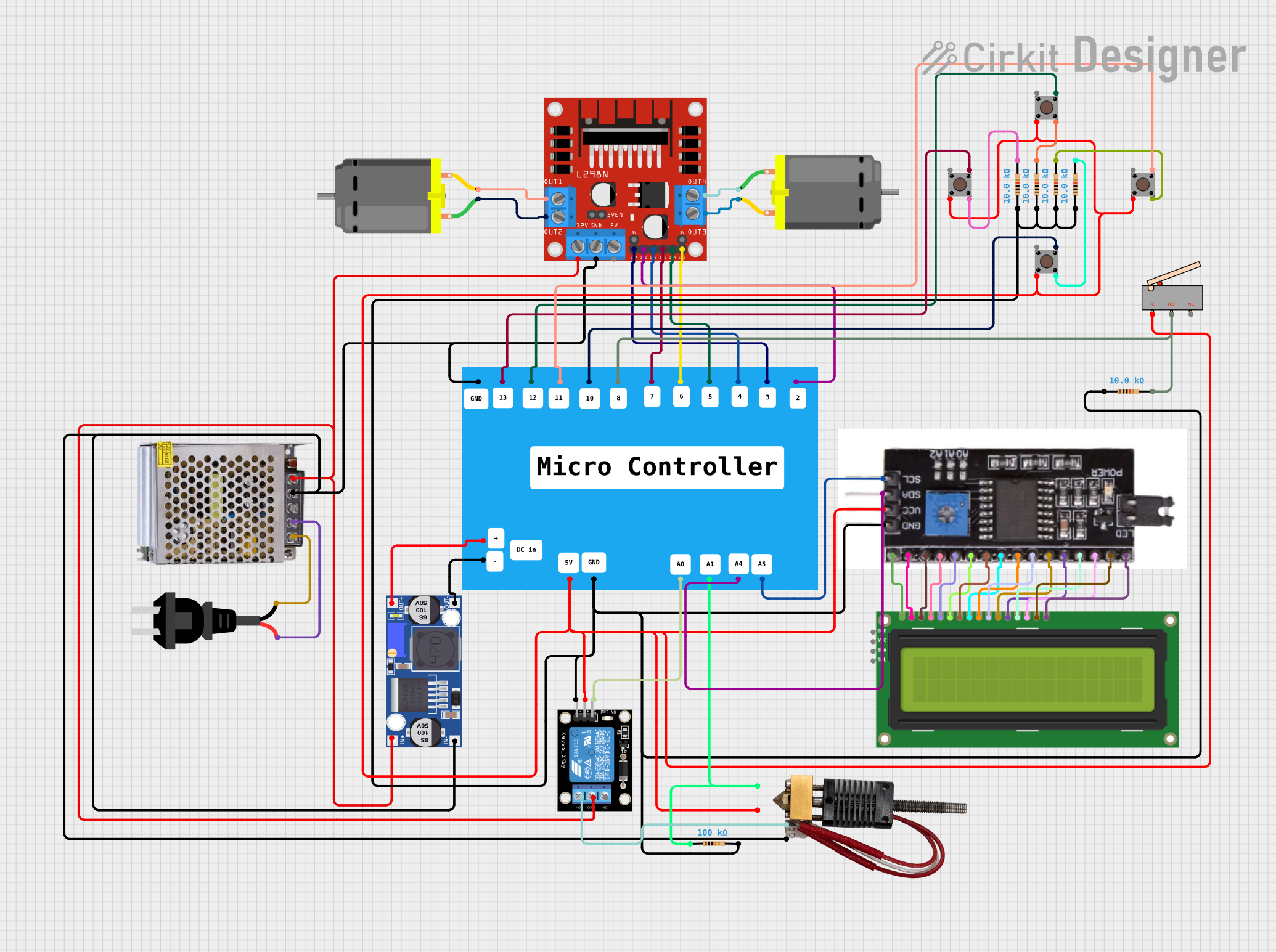

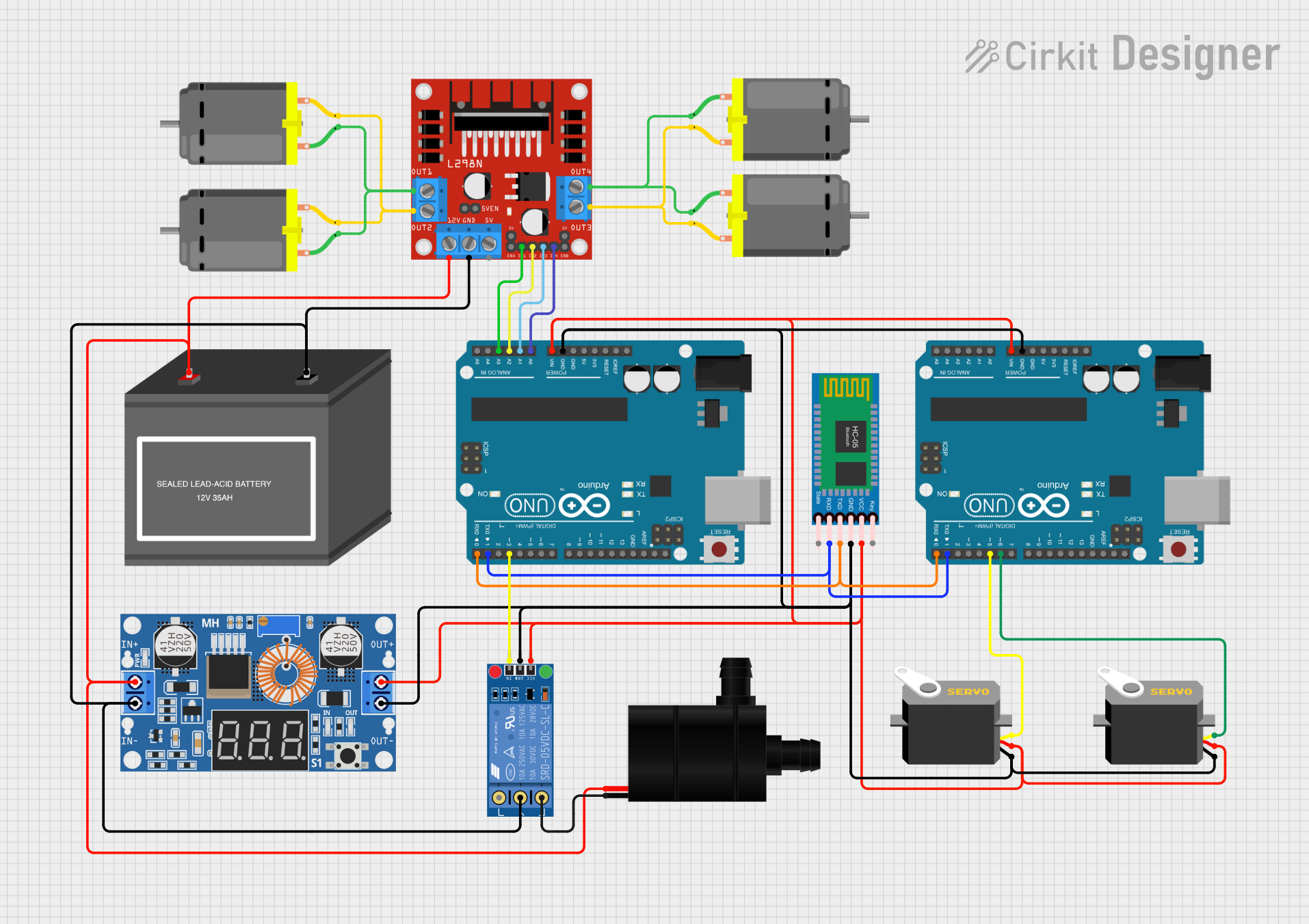
Explore Projects Built with L298 Dual H Bridge Motor Speed Controller
Common Applications and Use Cases
- Robotics: driving wheels or tracks
- CNC machines: controlling spindle and feed motors
- Home automation: operating blinds or curtains
- Hobby projects: RC cars, boats, and drones
Technical Specifications
Key Technical Details
- Operating Voltage (Vss): 4.5V to 7V
- Logic Supply Voltage (Vss): Up to 36V
- Peak Output Current (Io): 2A per channel
- Total Power Dissipation (Ptot): 25W
Pin Configuration and Descriptions
| Pin Number | Pin Name | Description |
|---|---|---|
| 1 | Vs | Power supply for the motors (up to 46V) |
| 2 | GND | Ground |
| 3 | Vss | Logic supply voltage (5V from Arduino) |
| 4 | Out 1 | Output to motor A terminal 1 |
| 5 | Out 2 | Output to motor A terminal 2 |
| 6 | Out 3 | Output to motor B terminal 1 |
| 7 | Out 4 | Output to motor B terminal 2 |
| 8 | EnA | Enable motor A, PWM input for speed control |
| 9 | In1 | Input 1 for motor A direction control |
| 10 | In2 | Input 2 for motor A direction control |
| 11 | In3 | Input 1 for motor B direction control |
| 12 | In4 | Input 2 for motor B direction control |
| 13 | EnB | Enable motor B, PWM input for speed control |
| 14 | GND | Ground |
| 15 | GND | Ground |
| 16 | GND | Ground |
Usage Instructions
How to Use the Component in a Circuit
- Connect the power supply for the motors to pin Vs and ground to GND pins.
- Connect the logic supply voltage (5V from Arduino) to Vss.
- Connect the motor terminals to Out 1 and Out 2 for motor A, and Out 3 and Out 4 for motor B.
- Connect the Arduino digital outputs to In1, In2, In3, and In4 for direction control.
- Connect the Arduino PWM outputs to EnA and EnB for speed control.
Important Considerations and Best Practices
- Ensure the power supply voltage does not exceed the maximum rating.
- Use appropriate heat sinks to manage heat dissipation.
- Avoid running motors at peak current for extended periods.
- Use flyback diodes across the motor terminals to protect against voltage spikes.
Example Arduino Code
// Define the L298N control pins
const int enA = 9;
const int in1 = 8;
const int in2 = 7;
const int enB = 3;
const int in3 = 5;
const int in4 = 4;

void setup() {
  // Set all the motor control pins to outputs
  pinMode(enA, OUTPUT);
  pinMode(enB, OUTPUT);
  pinMode(in1, OUTPUT);
  pinMode(in2, OUTPUT);
  pinMode(in3, OUTPUT);
  pinMode(in4, OUTPUT);
}

void loop() {
  // Turn on motor A & B
  digitalWrite(in1, HIGH);
  digitalWrite(in2, LOW);
  digitalWrite(in3, HIGH);
  digitalWrite(in4, LOW);

  // Set speed to 200 out of possible range 0-255
  analogWrite(enA, 200);
  analogWrite(enB, 200);

  delay(2000); // Run motors for 2 seconds

  // Now change motor directions
  digitalWrite(in1, LOW);
  digitalWrite(in2, HIGH);
  digitalWrite(in3, LOW);
  digitalWrite(in4, HIGH);

  delay(2000); // Run motors in the opposite direction for 2 seconds

  // Turn off motors
  digitalWrite(in1, LOW);
  digitalWrite(in2, LOW);
  digitalWrite(in3, LOW);
  digitalWrite(in4, LOW);
}
Troubleshooting and FAQs
Common Issues Users Might Face
- Motor not running: Check power supply and wiring connections.
- Overheating: Ensure proper heat sinking and avoid running at peak current for too long.
- Inconsistent motor speed: Verify PWM signal and ensure it is within the correct range.
Solutions and Tips for Troubleshooting
- Double-check all connections against the circuit diagram.
- Use a multimeter to verify the presence of voltage at the motor outputs.
- Ensure the logic supply voltage (Vss) is connected and at the correct level.
- Test the inputs (In1 to In4) with a simple HIGH/LOW output before using PWM.
FAQs
Q: Can the L298 drive stepper motors? A: Yes, the L298 can be used to drive stepper motors with the correct stepping sequence.
Q: What is the maximum current the L298 can handle? A: The L298 can handle up to 2A per channel, but it's recommended to stay below the peak current for continuous operation.
Q: Do I need to use external diodes with the L298? A: The L298 has built-in diodes for back EMF protection, but adding external diodes can provide additional protection.
Q: How do I control the speed of the motors? A: Speed control is achieved by applying PWM signals to the EnA and EnB pins. Adjusting the duty cycle of the PWM signal will vary the speed of the motors.