How to Use Connector 2 In 8 Out: Examples, Pinouts, and Specs
Introduction
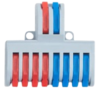
The Connector 2 In 8 Out is a versatile electronic component designed to distribute two input signals across eight output channels. This component is ideal for applications requiring signal routing, duplication, or distribution in complex circuits. It simplifies the process of managing multiple outputs from a limited number of inputs, making it a valuable tool in signal processing, audio systems, and control circuits.
Explore Projects Built with Connector 2 In 8 Out


Explore Projects Built with Connector 2 In 8 Out
Common Applications and Use Cases
- Signal distribution in audio systems (e.g., splitting audio signals to multiple speakers)
- Control signal routing in automation systems
- Data distribution in communication circuits
- Prototyping and testing circuits with multiple outputs
Technical Specifications
The Connector 2 In 8 Out is a passive component that does not amplify or modify the input signals. Below are its key technical details:
| Parameter | Value |
|---|---|
| Input Channels | 2 |
| Output Channels | 8 |
| Voltage Range | 0V to 24V (DC or AC signals) |
| Current Rating | Up to 1A per channel |
| Signal Type | Analog or Digital |
| Operating Temperature | -40°C to +85°C |
| Connector Type | Screw terminals or pin headers |
| Dimensions | 50mm x 30mm x 15mm |
Pin Configuration and Descriptions
The Connector 2 In 8 Out has a straightforward pin layout. Below is the pin configuration:
| Pin | Label | Description |
|---|---|---|
| 1 | IN1 | Input signal 1 |
| 2 | IN2 | Input signal 2 |
| 3-10 | OUT1-OUT8 | Output channels (OUT1-OUT4 for IN1, OUT5-OUT8 for IN2) |
| 11 | GND | Ground connection (common for all channels) |
Usage Instructions
How to Use the Component in a Circuit
- Connect the Inputs:
- Attach the first input signal to the
IN1pin. - Attach the second input signal to the
IN2pin.
- Attach the first input signal to the
- Connect the Outputs:
- The signals from
IN1will be distributed toOUT1,OUT2,OUT3, andOUT4. - The signals from
IN2will be distributed toOUT5,OUT6,OUT7, andOUT8.
- The signals from
- Ground Connection:
- Connect the
GNDpin to the ground of your circuit to ensure proper signal reference.
- Connect the
Important Considerations and Best Practices
- Signal Integrity: Ensure that the input signals are within the specified voltage and current ratings to avoid signal degradation or damage to the component.
- Load Matching: Verify that the connected loads on the output channels do not exceed the current rating of 1A per channel.
- Avoid Short Circuits: Double-check all connections to prevent short circuits, which could damage the component or other parts of the circuit.
- Use in Low-Noise Environments: For sensitive analog signals, use shielded cables to minimize noise interference.
Example: Connecting to an Arduino UNO
The Connector 2 In 8 Out can be used with an Arduino UNO to distribute digital signals. Below is an example of how to use it to control multiple LEDs:
Circuit Setup
- Connect
IN1to Arduino pin 8 andIN2to Arduino pin 9. - Connect
OUT1-OUT4to LEDs (via current-limiting resistors) forIN1. - Connect
OUT5-OUT8to LEDs (via current-limiting resistors) forIN2. - Connect the
GNDpin of the connector to the Arduino GND.
Arduino Code
// Example code to control LEDs using Connector 2 In 8 Out
// IN1 controls LEDs on OUT1-OUT4, IN2 controls LEDs on OUT5-OUT8

#define IN1_PIN 8  // Arduino pin connected to IN1
#define IN2_PIN 9  // Arduino pin connected to IN2

void setup() {
  pinMode(IN1_PIN, OUTPUT); // Set IN1 as output
  pinMode(IN2_PIN, OUTPUT); // Set IN2 as output
}

void loop() {
  digitalWrite(IN1_PIN, HIGH); // Turn on LEDs connected to OUT1-OUT4
  digitalWrite(IN2_PIN, LOW);  // Turn off LEDs connected to OUT5-OUT8
  delay(1000);                 // Wait for 1 second

  digitalWrite(IN1_PIN, LOW);  // Turn off LEDs connected to OUT1-OUT4
  digitalWrite(IN2_PIN, HIGH); // Turn on LEDs connected to OUT5-OUT8
  delay(1000);                 // Wait for 1 second
}
Troubleshooting and FAQs
Common Issues Users Might Face
No Signal on Output Channels:
- Cause: Input signal not connected or improperly connected.
- Solution: Verify that the input signals are properly connected to
IN1andIN2.
Signal Degradation:
- Cause: Exceeding the voltage or current rating.
- Solution: Ensure the input signals are within the specified voltage (0V to 24V) and current (up to 1A per channel).
Short Circuit on Outputs:
- Cause: Incorrect wiring or accidental shorting of output pins.
- Solution: Inspect the wiring and ensure no output pins are shorted.
Interference or Noise:
- Cause: Long unshielded cables or noisy environment.
- Solution: Use shielded cables and minimize cable length.
FAQs
Can this component handle AC signals?
- Yes, the Connector 2 In 8 Out can handle both AC and DC signals within the specified voltage and current range.
Can I use this component for high-frequency signals?
- This component is suitable for low to moderate frequency signals. For high-frequency applications, ensure proper impedance matching.
What happens if I connect only one input?
- If only
IN1is connected, onlyOUT1-OUT4will have signals. Similarly, if onlyIN2is connected, onlyOUT5-OUT8will have signals.
- If only
Is this component bidirectional?
- No, the Connector 2 In 8 Out is designed for unidirectional signal distribution from inputs to outputs.