
How to Use NodeMCU-32S ESP32 DEVKIT WROOM: Examples, Pinouts, and Specs
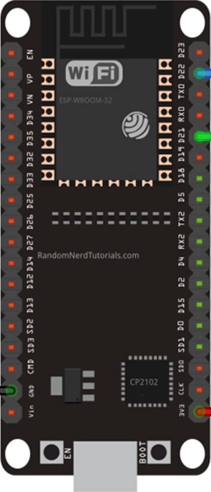
 Design with NodeMCU-32S ESP32 DEVKIT WROOM in Cirkit Designer
Introduction
The NodeMCU-32S ESP32 DEVKIT WROOM, manufactured by Wishiot (Part ID: CP2102), is a low-cost, open-source IoT development platform based on the powerful ESP32 chip. It features integrated Wi-Fi and Bluetooth capabilities, making it ideal for a wide range of applications, including home automation, sensor networks, and IoT prototyping. Its compact design and rich feature set make it a popular choice among developers and hobbyists.
Explore Projects Built with NodeMCU-32S ESP32 DEVKIT WROOM
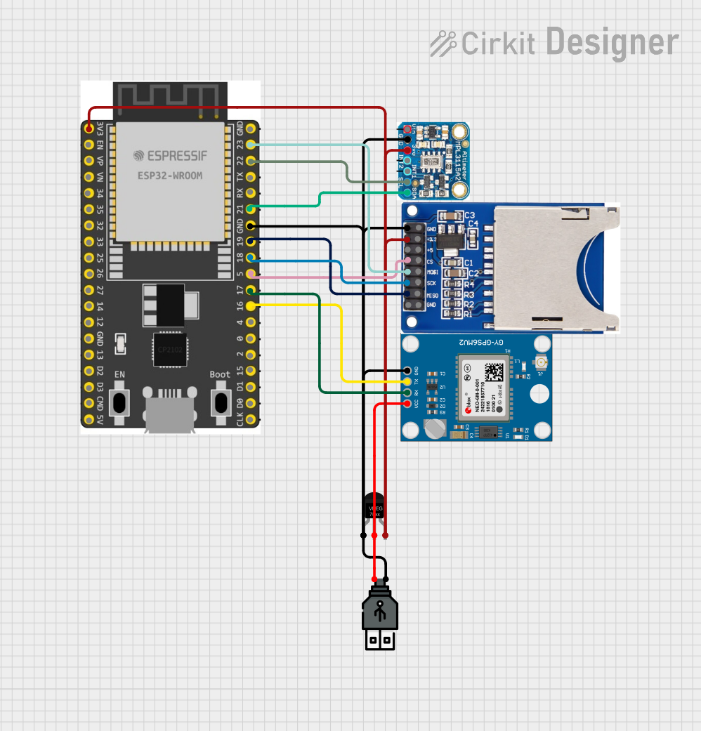 Open Project in Cirkit Designer
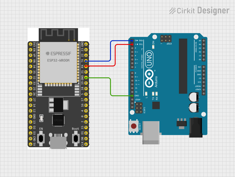 Open Project in Cirkit Designer
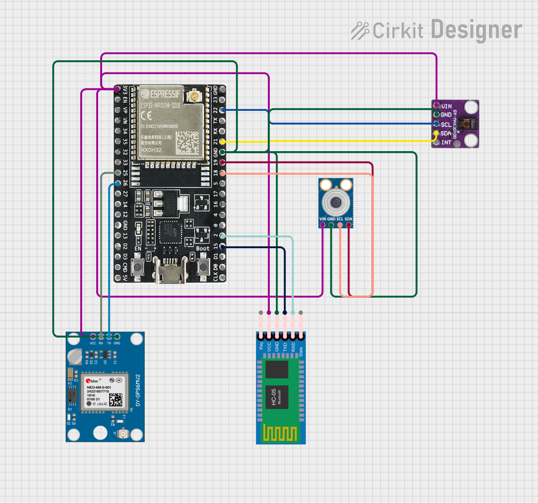 Open Project in Cirkit Designer
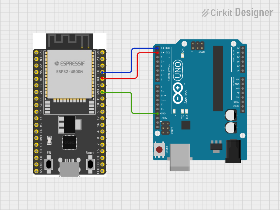 Open Project in Cirkit Designer
Explore Projects Built with NodeMCU-32S ESP32 DEVKIT WROOM
Open Project in Cirkit DesignerOpen Project in Cirkit DesignerOpen Project in Cirkit DesignerOpen Project in Cirkit DesignerCommon Applications:
- Home automation systems
- Wireless sensor networks
- IoT device prototyping
- Smart appliances
- Wearable devices
- Industrial IoT solutions
Technical Specifications
The NodeMCU-32S ESP32 DEVKIT WROOM is built around the ESP32-WROOM-32 module, which integrates a dual-core processor, wireless connectivity, and a variety of peripherals.
Key Technical Details:
| Parameter | Specification |
|---|---|
| Microcontroller | ESP32 (Xtensa® dual-core 32-bit LX6) |
| Clock Speed | Up to 240 MHz |
| Flash Memory | 4 MB (SPI Flash) |
| SRAM | 520 KB |
| Wi-Fi | 802.11 b/g/n (2.4 GHz) |
| Bluetooth | v4.2 BR/EDR and BLE |
| Operating Voltage | 3.3 V |
| Input Voltage (VIN) | 5 V (via USB or external power) |
| GPIO Pins | 30 |
| ADC Channels | 18 (12-bit resolution) |
| DAC Channels | 2 |
| Communication Interfaces | UART, SPI, I2C, I2S, CAN, PWM |
| USB-to-Serial Chip | CP2102 |
| Dimensions | 58 mm x 25.5 mm |
Pin Configuration and Descriptions:
The NodeMCU-32S ESP32 DEVKIT WROOM has a total of 38 pins. Below is a summary of the key pins:
| Pin Name | Pin Number | Description |
|---|---|---|
| VIN | 1 | Input voltage (5 V) |
| GND | 2, 38 | Ground |
| 3V3 | 3 | 3.3 V output |
| EN | 4 | Enable pin (active high) |
| IO0 | 5 | GPIO0, used for boot mode selection |
| IO2 | 6 | GPIO2, supports PWM, ADC, etc. |
| IO4 | 7 | GPIO4, supports PWM, ADC, etc. |
| IO5 | 8 | GPIO5, supports PWM, ADC, etc. |
| IO12 | 9 | GPIO12, supports PWM, ADC, etc. |
| IO13 | 10 | GPIO13, supports PWM, ADC, etc. |
| IO14 | 11 | GPIO14, supports PWM, ADC, etc. |
| IO15 | 12 | GPIO15, supports PWM, ADC, etc. |
| IO16 | 13 | GPIO16, supports UART, ADC, etc. |
| IO17 | 14 | GPIO17, supports UART, ADC, etc. |
| IO18 | 15 | GPIO18, supports SPI, PWM, etc. |
| IO19 | 16 | GPIO19, supports SPI, PWM, etc. |
| IO21 | 17 | GPIO21, supports I2C, PWM, etc. |
| IO22 | 18 | GPIO22, supports I2C, PWM, etc. |
| IO23 | 19 | GPIO23, supports SPI, PWM, etc. |
| IO25 | 20 | GPIO25, supports DAC, ADC, etc. |
| IO26 | 21 | GPIO26, supports DAC, ADC, etc. |
| IO27 | 22 | GPIO27, supports ADC, PWM, etc. |
| IO32 | 23 | GPIO32, supports ADC, PWM, etc. |
| IO33 | 24 | GPIO33, supports ADC, PWM, etc. |
| IO34 | 25 | GPIO34, input-only ADC |
| IO35 | 26 | GPIO35, input-only ADC |
| IO36 | 27 | GPIO36, input-only ADC |
| IO39 | 28 | GPIO39, input-only ADC |
Usage Instructions
How to Use the NodeMCU-32S ESP32 DEVKIT WROOM in a Circuit:
Powering the Board:
- Connect the board to a computer or USB power source using a micro-USB cable.
- Alternatively, supply 5 V to the VIN pin and connect GND to ground.
Programming the Board:
- Install the CP2102 USB-to-Serial driver (if not already installed).
- Use the Arduino IDE or ESP-IDF (Espressif IoT Development Framework) to write and upload code.
- Select the correct board (
NodeMCU-32S) and port in the IDE.
Connecting Peripherals:
- Use the GPIO pins to connect sensors, actuators, or other devices.
- Ensure that the voltage levels of connected devices are compatible with the 3.3 V logic of the ESP32.
Flashing Code:
- Hold the
BOOTbutton while pressing theENbutton to enter flashing mode. - Release the
BOOTbutton and upload the code from the IDE.
- Hold the
Example Code for Arduino IDE:
The following example demonstrates how to blink an LED connected to GPIO2:
// Define the GPIO pin for the LED
#define LED_PIN 2

void setup() {
  pinMode(LED_PIN, OUTPUT); // Set GPIO2 as an output pin
}

void loop() {
  digitalWrite(LED_PIN, HIGH); // Turn the LED on
  delay(1000);                 // Wait for 1 second
  digitalWrite(LED_PIN, LOW);  // Turn the LED off
  delay(1000);                 // Wait for 1 second
}
Important Considerations:
- Voltage Levels: Ensure that all connected peripherals operate at 3.3 V logic levels. Use level shifters if necessary.
- Power Supply: Avoid powering high-current devices directly from the 3V3 pin. Use an external power source if needed.
- Boot Mode: GPIO0 must be pulled low during boot to enter flashing mode.
Troubleshooting and FAQs
Common Issues:
Board Not Detected by Computer:
- Ensure the CP2102 driver is installed correctly.
- Try a different USB cable or port.
Code Upload Fails:
- Check that the correct board and port are selected in the IDE.
- Hold the
BOOTbutton while uploading the code.
Wi-Fi Connection Issues:
- Verify the SSID and password in your code.
- Ensure the router operates on the 2.4 GHz band (ESP32 does not support 5 GHz).
GPIO Pin Not Working:
- Confirm that the pin is not reserved for internal functions (e.g., GPIO0, GPIO2 during boot).
- Check for wiring or connection issues.
Tips for Troubleshooting:
- Use the serial monitor to debug and view error messages.
- Test the board with a simple sketch (e.g., blinking an LED) to verify functionality.
- Refer to the ESP32 datasheet for detailed information on pin functions and electrical characteristics.